42 OPERATION AND INSTALLATION INSTRUCTIONS MN280075EN July 2018
Form 6 microprocessor-based rack-mount recloser control
3
6
4
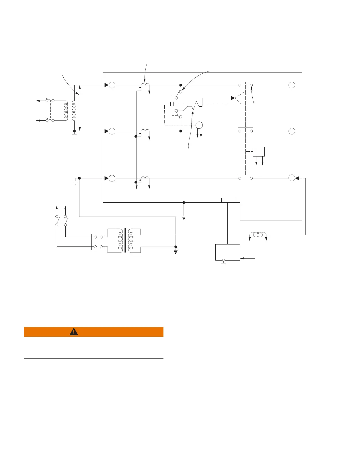
T3
Y
H*
X
Z
VOLTAGE RATING OF
RECLOSER CLOSING
SOLENOID COIL
SENSING CTs (3)
CLOSING
SOLENOID
CONTACTOR
ROTARY
SOLENOID
MAIN
CONTACTS (S)
G*K*
A* B*
E* F*
TO
240 OR
480 VAC
SOURCE
TO
240 VAC
SOURCE
CLOSING
SOLENOID
COIL
TRIP
SOLENOID
CONTROL
CABLE RECEPTACLE
W
FORM 6
CONTROL
TO
AMMETER AND RELAY TO
OPERATE CYCLE COUNTER
OR OTHER TIMING DEVICE
AC POWER
VARIABLE
AUTOTRANSFORMER
240 VAC
20 AMPS
T2
1
2
5
J*
T1
*Indicates control cable receptacle pin/socket designation.
Figure38. Suggested test circuit for high voltage “shop-testing” solenoid-closing reclosers
Electrical closing – motor-operated
low voltage closing solenoid / auxiliary-powered
NOVA reclosers
WARNING
Hazardous voltage. Solidly ground all equipment.
Failure to comply can result in death, severe personal
injury, and equipment damage. T223.2
High-voltage is not required for reclosers utilizing a
motor-operated closing mechanism, low voltage closing,
or Auxiliary-Powered NOVA recloser. For information on
energizing the recloser, refer to the appropriate recloser
installation manual. Low voltage supply can use either 120
or 240 VAC for input power. Check the name plate on the
recloser to verify the correct closing power requirements.
Figure39 shows a test circuit for motor-operated,
low-voltage solenoid-closing, and Auxiliary-Powered NOVA
reclosers. Since these reclosers require only a low voltage
source for closing, high-voltage transformer T3 and its
protective cage is eliminated. All other equipment is the
same as the test equipment shown in Figure38.
 Loading...


