15
SPEAR™ Single-Phase Recloser System
INSTALLATION AND OPERATION INSTRUCTIONS MN280048EN June 2016
Figure 14. Cable with cable coupler ring
A. Provide surge protection to both sides of the
recloser.
ote:N The horizontal bushing is the source side and the
vertical bushing is the load side. See Figure 16.
B. Connect high-voltage lines to recloser bushing
terminals. The recommended torque value for
bushing terminal-to-line connection is 45-50 ft•lbs.
Refer to Figure 16 for terminal identification of the
SPEAR single-phase recloser.
Terminal connection to only copper conductors is
recommended.
CAUTION
Equipment damage. Do not adjust or rotate bushing
terminals without first removing power line leads
and loosening pinch bolt to release clamp tension.
Failure to remove tension between the clamp and
the interrupter stud prior to rotating the terminal will
damage the encapsulated interrupter assembly resulting
in equipment damage.
T347.0
CAUTION
Equipment damage may occur if torque values are
exceeded.
T370.0
To rotate a flat-pad or eyebolt bushing terminal
prior to connecting power line leads, loosen the
pinch bolt on the terminals. After rotating the
terminal, retighten the pinch bolt as follows: torque
3/8-16 pinch bolts to 15–17 ft•lbs (20–23 Nm);
torque 1/2-13 pinch bolts to 29–31 ft•lbs (39–42
Nm).
Figure 15.
Surge
Switch
Surge
Recloser
Connection diagram showing complete surge
protection with bypass and disconenct switches
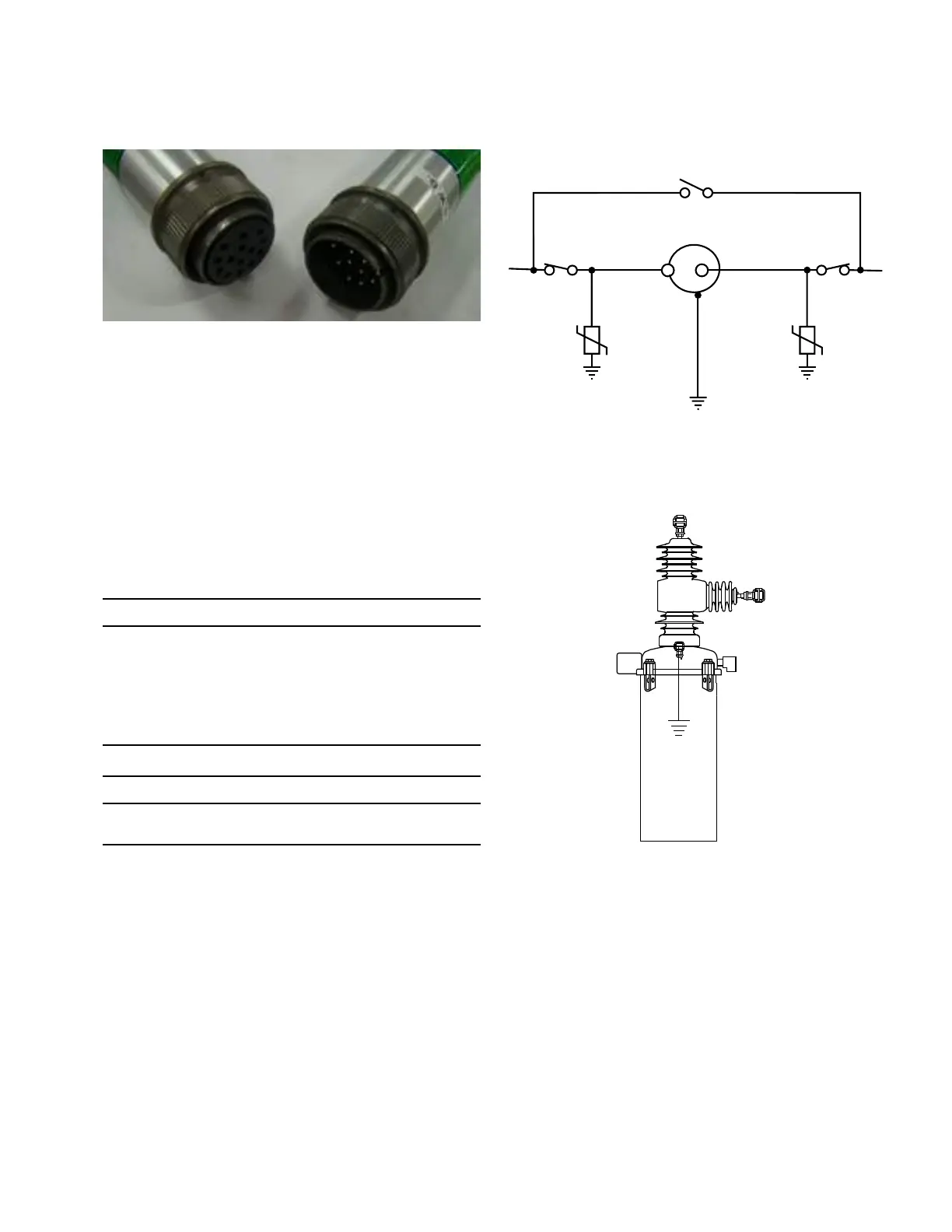
Figure 16.
Source
Load
Terminal identification of SPEAR single-phase
recloser
8. Close source and load disconnect switches.
9. Close recloser via control signal.
10. Open bypass switches.
 Loading...


