PHASE FAULT
A B C
GROUND FAULT
ABOVE MIN TRIP
LOCKOUT
OPEN
CLOSED
VOLTAGE TRIP
FREQUENCY TRIP
SENSITIVE GND
A B C
X Y Z
PHASE VOLTAGE
ALARM
BATTERY
AC POWER
CONTROL OK
ALT
PROFILE 1
GND TRIP
BLOCKED
NON
RECLOSE
SUPER-
VISORY
OFF
HOT LINE
TAG
TRIP
OFF
(LOCKOUT)
CLOSE
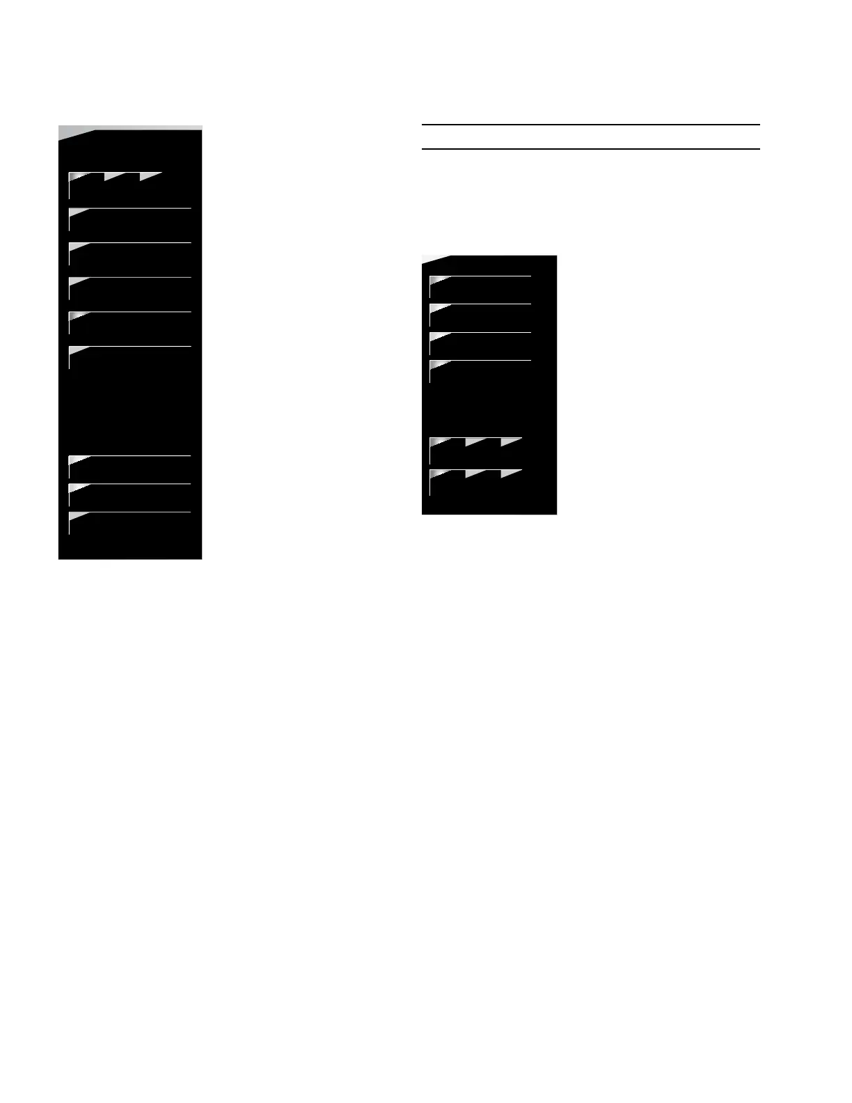
Figure 5. Form 4D Pole-mount control status indicator
LEDs (left side)
ABOVE MIN TRIP: This LED illuminates when the control
detects that current is above the programmed minimum trip
value for Bushings 1-2, Bushings 3-4, Bushings 5-6, Ground
or Sensitive Ground.
LOCKOUT: This LED illuminates to indicate the control is in a
locked out state, i.e. a reclosing sequence is not in progress.
This LED does not indicate that the recloser is open.
OPEN: This LED illuminates to indicate the recloser is in the
open position.
CLOSED: This LED illuminates to indicate the recloser is in
the closed position.
ote:N There are several conditions that will cause the
alternate blinking of the control LOCKOUT, recloser
OPEN, and recloser CLOSED LEDs: Failure to Trip,
Failure to Close, Interrupter Malfunction, and 52a/b
Disagreement.
The LED blinking pattern for these conditions is the
control LOCKOUT LED and recloser CLOSED LED
alternating with the recloser OPEN LED.
ote:N Function Code 80 Reset Targets will clear the
Interrupter Malfunction diagnostic. The alarm
LED will remain illuminated as long as the alarm
condition exists.
IMPORTANT
The CLOSED LED will blink and a countdown-to-close
timer will appear on the LCD display when a delayed
CLOSE is active. A CLOSE will occur when the manual
close delay timer expires.
This information is indicated on the right side of the control:
(Figure 6):
DATA PORTS
ENTER
EDIT
ESC
PHASE FAULT
A B C
GROUND FAULT
ABOVE MIN TRIP
LOCKOUT
OPEN
CLOSED
VOLTAGE TRIP
FREQUENCY TRIP
SENSITIVE GND
A B C
X Y Z
PHASE VOLTAGE
ALARM
BATTERY
AC POWER
CONTROL OK
ALT
PROFILE 1
GND TRIP
BLOCKED
NON
RECLOSE
SUPER-
VISORY
OFF
HOT LINE
TAG
TRIP
OFF
(LOCKOUT)
CLOSE
Figure 6. Form 4D Pole-mount control status indicator
LEDs (right side)
ALARM: This LED illuminates to indicate an alarm condition
exists. The LED will flash for unacknowledged alarms, and
will continuously illuminate for acknowledged alarms that
are still active. Refer to Service Information S280-104-2
Form 4D Microprocessor-Based Recloser Control
Programming Guide for alarm list.
These Status Alarms are enabled by default:
AC Power present.
Aux Power Failure.
Battery Disconnect.
Battery Failure.
Battery Trouble.
Clock Not Set.
Control Circuit Interrupted.
Interrupter Malfunction.
Recloser Closed: Failed to Trip.
Recloser Open: Failed to Close.
State Indeterminate Open and Closed.
6 OPERATION INSTRUCTIONS MN280049EN September 2017
Form 4D Microprocessor-based pole-mount recloser control installation and operation instructions
 Loading...


