IMPORTANT
To enable or disable specific alarms, use the ProView
NXG software to configure the alarms. Refer to Section
5: Alarms in Service Information S280-104-2 Form 4D
Microprocessor-Based Recloser Control Programming
Guide. If alarms are not configured, the ALARM LED will
not illuminate.
CAUTION
Loss of protection. Reconfigure the user settings. When
the CONTROL OK LED is flashing, control protection
is disabled. User protection profile settings must be
reconfigured to enable protection. Loss of protection can
result in personal injury and equipment damage.
T360.1
CONTROL OK: This indicator illuminates to indicate that
the control passed self-diagnostics and is capable of
normaloperation.
ote:N A flashing CONTROL OK LED indicates a problem
with user settings. Default settings will be displayed
under these circumstances, but protection has been
disabled. User protection profile settings must be
reconfigured to enable protection.
When the CONTROL OK LED is flashing, the
following message appears on the LCD display upon
power-up:
Protection Disabled. Change Protection Settings.
Press ESC to Clear Message.
As soon as the HMI goes into power save mode
(inactivity for 15 minutes) the message will no longer
display on the LCD, but the CONTROL OK LED will
continue to flash to indicate protection is disabled.
AC POWER: This indicator is illuminated when the presence
of AC input power to the control is sensed.
BATTERY: This LED illuminates to indicate battery voltage is
low or the battery failed a battery test.
PHASE VOLTAGE A PHASE VOLTAGE X
PHASE VOLTAGE B PHASE VOLTAGE Y
PHASE VOLTAGE C PHASE VOLTAGE Z
These LED indicators illuminate when the control detects
the presence of voltage greater than the “V present”
setting on the System Configuration dialog. The LED will go
out if the voltage on that phase is less than 95% of the “V
present” setting.
If the appropriate phantom phase reference value is above
the specified “V present” setting, all three LEDs (source
or load) will illuminate. All three LEDs will extinguish if the
reference voltage falls below 95% of the “V present” setting.
Refer to Service Information S280-104-2 Form 4D
Microprocessor-Based Recloser Control Programming Guide
for information regarding nominal voltage specification via the
System Configuration dialog in ProView NXG software.
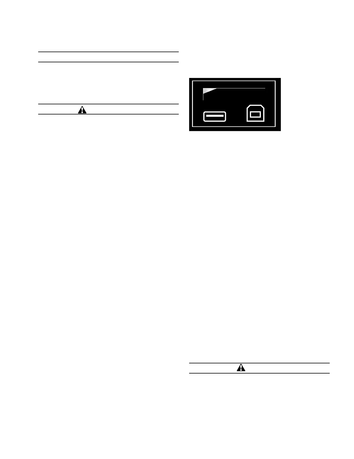
DATA PORTS
The DATA PORTS section (Figure 7) on the front operating
panel allows for direct connection to a personal computer.
DATA PORTS
ENTER
EDIT
ESC
PHASE FAULT
A B C
GROUND FAULT
ABOVE MIN TRIP
LOCKOUT
OPEN
CLOSED
VOLTAGE TRIP
FREQUENCY TRIP
SENSITIVE GND
A B C
X Y Z
PHASE VOLTAGE
ALARM
BATTERY
AC POWER
CONTROL OK
ALT
PROFILE 1
GND TRIP
BLOCKED
NON
RECLOSE
SUPER-
VISORY
OFF
HOT LINE
TAG
TRIP
OFF
(LOCKOUT)
CLOSE
Figure 7. DATA PORTS section
The left port is a host port used for connecting to a USB
flash memory device to upload or download data and
settings files or to upgrade the firmware. All settings,
metering, alarms, and sequence of events are available
from this port.
The Data Port LED is illuminated when the USB memory
stick is inserted and properly detected.
The right port is a client port used to communicate with
the control from a personal computer. This port is used
for accessing the control with ProView NXG application
software. All settings, metering, alarms, and events are
available from this port.
Operating panel
TRIP (Lockout) Pushbutton
The TRIP pushbutton (Figure 8) provides front-panel access
to trip (lockout) the recloser. When pressed, the TRIP
pushbutton opens the recloser and locks out the control.
Control power is required for the TRIP button to issue a
command to the recloser.
CLOSE Pushbutton
When pressed, the CLOSE pushbutton (Figure 8) returns
the control to the initial or home sequence position, closing
the recloser. The control is ready for the start of a new trip/
close sequence.
ote:N Pressing the CLOSE pushbutton from the Lockout
position initiates Cold Load Pickup (CLPU) protection,
if the feature is enabled, and the recloser has been
open longer than the CLPU minimum open time.
HOT LINE TAG ON/OFF Toggle Switch and LED Indicator
WARNING
Hazardous voltage. Do not use Hot Line Tag as a
substitute for a visible disconnect. Always establish a
visible disconnect prior to performing any work requiring
a de-energized line. Failure to comply may cause death,
severe personal injury, or equipment damage.
T276.0
7OPERATION INSTRUCTIONS MN280049EN September 2017
Form 4D Microprocessor-based pole-mount recloser control installation and operation instructions
 Loading...


