Catalog data MN650002EN
Effective February 2019
Deadbreak apparatus connectors
Step 2.
Remove concentric neutral wires or jacket
ote:N Care should be taken to not cut or score the
neutral conductors when cutting the cable jacket.
•
Measure 13" (330 mm) from end of cable.
Refer to Figure 15.
• For jacketed neutral cable, remove jacket to
13" dimension.
• For unjacketed neutral cable, bind neutral wires using
three (3) wraps of tape at 13" dimension.
•
Pull back concentric neutral wires. Allow enough extra
concentric neutral wires to connect to ground after installation
and allow movement to insulated standoff bushing.
Step 3.
Remove insulation shield
•
Remove insulation shield 10 1/2" (267 mm) from end of
cable. Refer to Figure 16.
•
Do not cut or nick insulation.
Step 4.
Put tape marker in place
•
Measure 1" (25 mm) from end of insulation shield.
(Refer to Figure 16.)
•
Wrap two turns of tape to serve as marker for cable
adapter location.
Step 5.
Remove conductor insulation
ote:N Do not pencil cable.
•
Remove insulation exposing bare conductor to length of
4 1/2" (114 mm). Refer to Figure 17.
ote:N Do not unwind conductor strands.
Step 6.
Bevel insulation
•
Remove sharp edge of insulation by beveling at a 45°
angle for approximately 1/4" (6 mm). (Refer to Figure 18.)
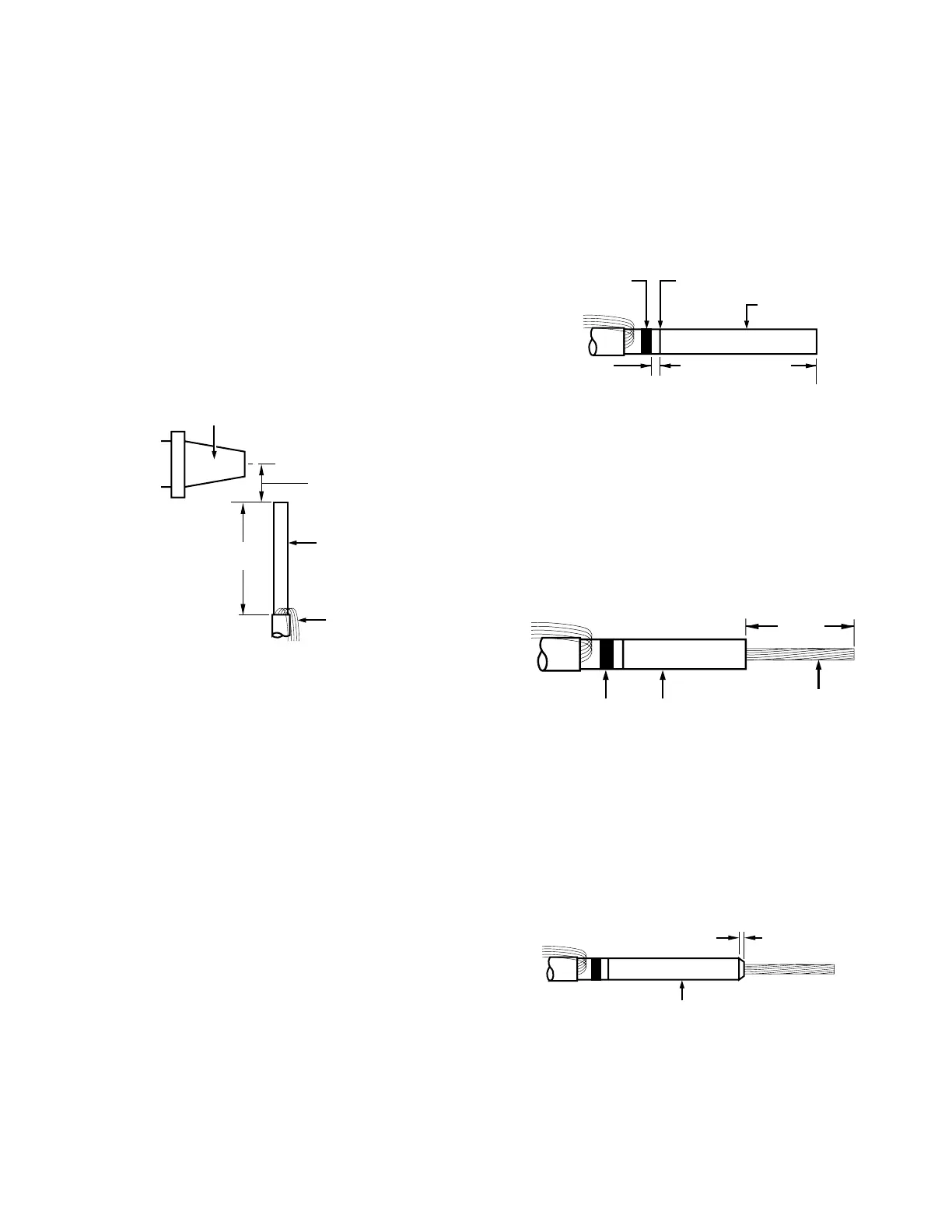
Figure 15. Line illustration of removing concentric
neutral wires.
Bushing
Cable
1 3/4" ± 1/4"
(44 mm ± 6 mm)
13" ± 1/4"
(330 mm ± 6 mm)
Concentric neutral
wires
Figure 16. Line illustration of cable stripback.
10 1/2" ± 1/8"
(267 mm ± 3 mm)
1"
(25 mm)
Tape marker Insulation shield
Insulation
Figure 17. Line illustration of bare conductor length.
4 1/2" ± 1/8"
(114 mm ± 3 mm)
Tape marker
Bare conductor
Insulation
Figure 18. Line illustration of insulation bevel.
Bevel
Insulation
1/4"
(6 mm)
9
600 A 35 kV class BOL-T connector assembly installation instructions MN650002EN February 2019
 Loading...


