•
Unthread hitch pin.
•
Grasp latch handle of PUSH-OP connector (mounted
on insulated standoff bushing) using hotstick and pull
backward until connector is completely unseated. Refer
to Figure 19.
•
Grasp PUSH-OP connector operating eye with hotstick.
Pull eye completely into hotstick. Move connector to
apparatus bushing, engaging shroud locating pins in
bail bracket locking slots until latch plate engages first
notches. Refer to Figure 20.
•
Push forward on push plate with hotstick until a bump
is felt and latch plate has engaged locking teeth. Pull on
push plate with hotstick to ensure latch plate is engaged.
Refer to Figure 21.
•
Thread hitch pin clockwise until bail lock is secured.
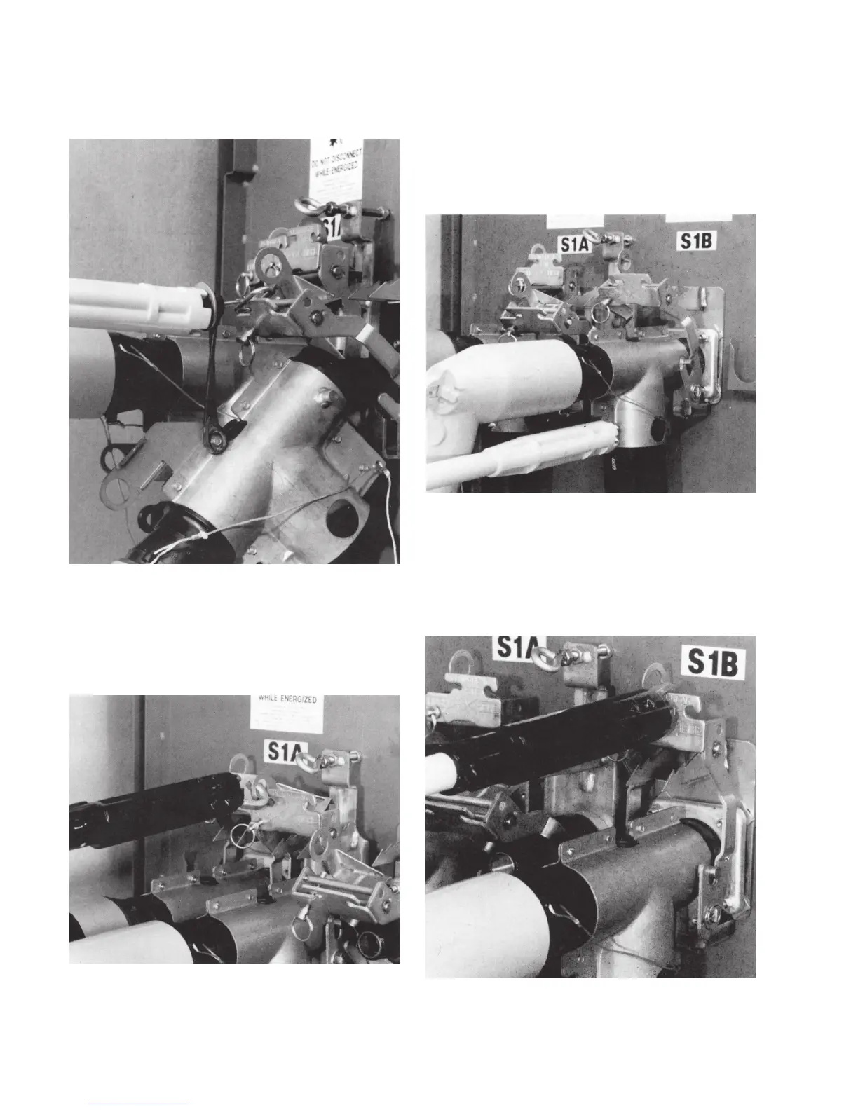
Figure 18. Pull back until bushing adapter is unsealed.
Figure 19. Pull back until connector is unsealed.
Figure 20. Move connector to apparatus bushing.
Figure 21. Pull on push plate to ensure latch plate is
engaged.
8 600 A PUSH-oP DeADbreAk connector oPerAtion inStrUctionS MN650011EN May 2017
 Loading...


