•
Remove grounding elbow from connector using hotstick.
•
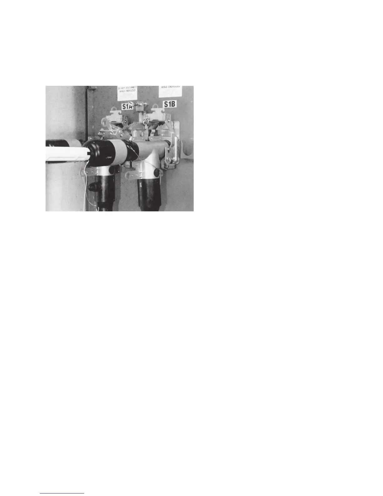
Place 200 A insulated protective cap or arrester on 200 A
connector interface using hotstick. Refer to Figure 22.
Repeat Steps 1 and 2 for all three phases on both ends
of cable. Remove all tool, test equipment and personal
protective equipment from work area before energizing
apparatus.
Figure 22. Place cap on 200 A connector interface.
9600 A PUSH-oP DeADbreAk connector oPerAtion inStrUctionS MN650011EN May 2017
 Loading...


