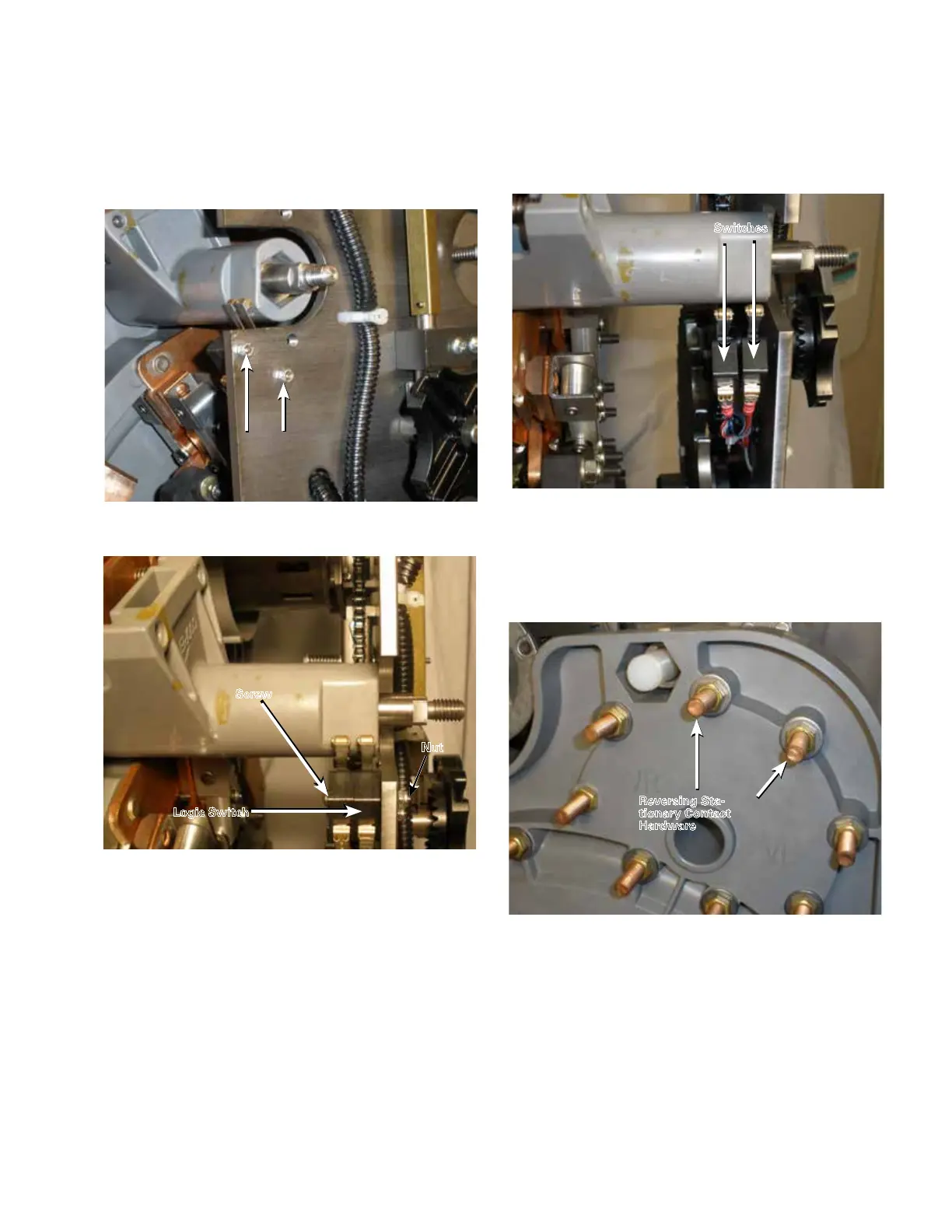
5. Use a small screw driver (or 5/32" Allen wrench) and
a 1/4" wrench to loosen and remove the self-locking
nuts and reversing logic switch mounting screws. See
Figures 33 and 34.
6. After removing the reversing logic switch mounting
screws the switch will drop away from the reversing
movable switch tube. See Figure 35.
7. Use a 9/16" wrench to loosen and remove the nuts
and flat washers from both of the reversing neutral
stationary contacts on the back of the tap-changer
contact panel. See Figure 36.
Figure 34. Removal of logic switch.
Nut
Screw
Logic Switch
Figure 35. Loose logic switches.
Switches
Figure 36. Reversing neutral stationary contact.
Figure 33. Reversing logic hardware.
Logic switch
Hardware
Reversing Sta-
tionary Contact
Hardware
17
QD5 QUIK-DRIVE TAP-CHANGER INSTALLATION AND MAINTENANCE INSTRUCTIONS MN225012EN March 2016
 Loading...


