2
3
4
5
6
7
8
8
9
10
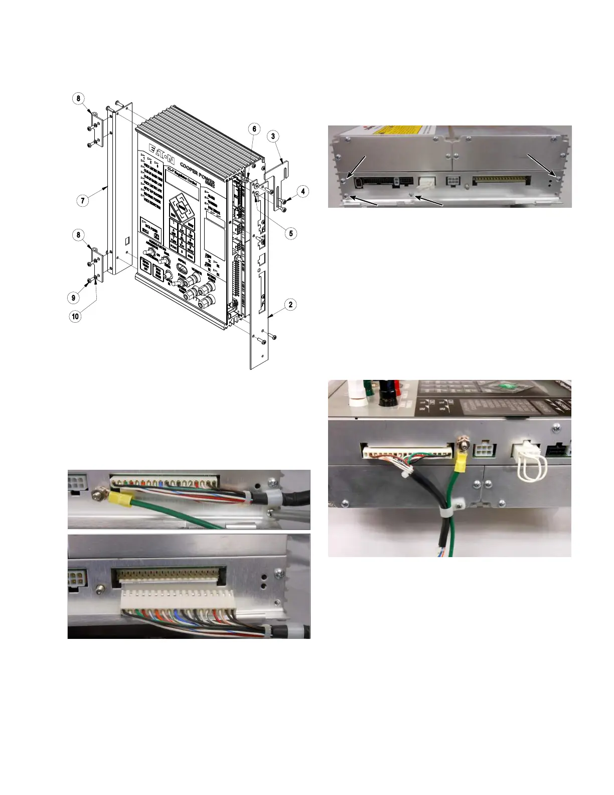
Figure 43. Installing hinge and latch bracket assemblies
5. Remove the strain relief screw (retain the screw and
strain relief device) and disconnect the white connector
from the side of the CL-7 control panel. See Figure 44.
6. Using a 3/8-inch wrench, remove the green ground
wire from the side of the panel; retain the washer and
nut. See Figure 44.
Figure 44. Removal of existing ground wire and wiring
harness
7. Remove the remaining four screws holding on the
hinged side panel; retain the screws. See Figure 45.
8. Install the right faceplate on the side of the control
using the screws retained from Step 5 and the last
step. See Figure 43.
Figure 45. Removal of hinged side panel from CL-7
control
9. Install the latch (Item3) on the right faceplate using
the shoulder screws (Item4) and washers (Item5) as
shown in Figure 43.
10. Install the Howard Industries wiring harness (Item1).
See Figure 46.
11. Install the extended green ground wire (Item11)
using the washer and nut retained from Step 6. See
Figure 46.
12. Route the wiring harness and ground wire through the
strain relief device and secure using a screw as shown
in Figure 46.
Figure 46. Installing ground wire and Howard Industries
wiring harness
13. Install the adhesive cable-tie anchors (Item12) as
shown in Figure 47 and secure the wiring harness and
ground wire using the cable ties (Item13). Trim back
the cable ties as necessary.
17
CL-7 Control Panel Retrofit
InstallatIon InstructIons MN225018EN April 2018
 Loading...


