12 OPERATION AND INSTALLATION INSTRUCTIONS MN280075EN July 2018
Form 6 microprocessor-based rack-mount recloser control
TB1
1
2
3 57911 13 15 17 19
46 81012141618
CI1
CI2 CI3 SS1 CO1
CO2 CO3 CO4
CI4
CI1 CI2 CI3 SS1 CO1 CO2 CO3 CO4
TB3
1
3
579111315171921
CI5 CI6 CI7 CI8 CI9 CI10 CI11 CO5 CO6
TB4
2
46 81012141618
20
CI4 CI5 CI6 CI7 CI8 CI9 CI10 CI11 CO5
CO6
13
5
7911 13
CO7 CO8
CO9 CO10 CO11
CO12
2
46 81012
CO7 CO8 CO9 CO10 CO11 CO12
FUSE
(10 AMP)
FUSE
(10 AMP)
TB5
+
1
-
5
2
-
4
+
INPUT POWER AUXILIARY POWER
28 VDC
RECLOSER INTERFACE CONNECTIONS
A
1
D
3
F
57
2
B
4
C
6
E
TB6
TB2
•
12
•
34
•
56
•
78
•
910
•
11 12
•
13 14
•
15 16
•
17 18
•
19
20
I
(1-2)
I(3-4) I(5-6) V(1-2)
V(3-4) V(5-6) V1
I(SEF)
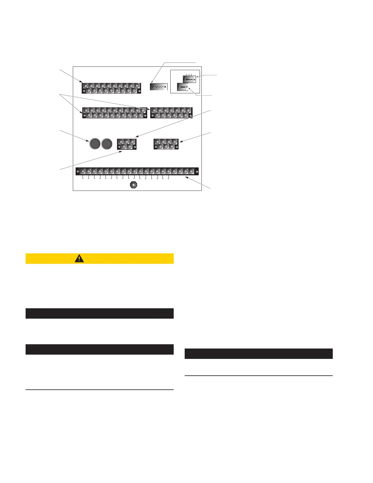
Three Control Input
and Five Status
Output Contacts
(Standard Feature)
Eight Control Inputs
and Eight Status
Outputs (Accessory)
Fuses
125 VDC
10 Amp
VDC Power Input
Connections
28 VDC Auxiliary
Power Connections
Recloser Interface
Terminal Block
Analog Connections
Terminal Block for
Connecting to Recloser,
Voltage Inputs
J1-RS-232
IRIG-B
RS-485
RS-232 DTE
RS-232 Serial Communication Port
Fiber Optic port, "ST" Type Connector (optional),
Ethernet Port, "MT-RJ" Fiber RJ45 Connector (optional)
RS-485 Serial Communication Port (optional)
C + –
IRIG-B Time Sync Connector
Figure7. Rack mount control back panel
Installation procedure
Initial programming prior to installation
CAUTION
Equipment misoperation. Do not connect this control
to an energized recloser until all control settings have
been properly programmed and verified. Refer to the
programming information for this control. Failure to
comply can result in control and recloser misoperation,
equipment damage, and personal injury. G110.3
IMPORTANT
Equipment misoperation. Check minimum trip values prior
to changing an alternate profile. Failure to do so may cause
misoperation of the recloser under loadconditions. T280.1
IMPORTANT
Program all protection profiles. Unused alternate profiles
should be programmed with the same settings as one of
the applicable profiles. Default settings on unused alternate
profiles can cause unnecessary outages if they are below
normal system requirements.
The control must be programmed with all necessary
operating settings, all alternate profiles, and parameters
prior to operation with an energized recloser.
ote:N Initial programming of the control is the responsibility
of a qualified technician or engineer familiar with
control functions and programming parameters
required for the specific recloser installation.
The control must be programmed with the Form 6 ProView
interface software. Refer to Service Information S280-70-4
(ProView 4.X.X) or S280-70-21 (ProView 5.X.X) Form 6
Control Programming Guide for additional information.
Control/recloser compatibility
The Form 6 rack mount recloser control is adaptable to the
following Eaton Cooper Power series reclosers:
WE*, WVE27, WVE38X, VWE, VWVE27, VWVE38X,
VSA12, VSA16, VSA20, VSA12B, VSA20A, VSO12, VSO16,
Auxiliary-Powered NOVA reclosers.
* This control is not compatible with Form 1 Type WE
reclosers below s/n 300 and RE reclosers below s/n 400.
IMPORTANT
All Auxiliary-Powered NOVA reclosers require power at the
input power receptacle for tripping and closing.
A new control cable is required to connect the Form 6 rack
mount recloser control to these reclosers. Refer to Table3
in the Recloser connections/control cable Section of the
Customer connections for DC power and AC voltage
sensing section of this manual.
 Loading...


