18 OPERATION AND INSTALLATION INSTRUCTIONS MN280075EN July 2018
Form 6 microprocessor-based rack-mount recloser control
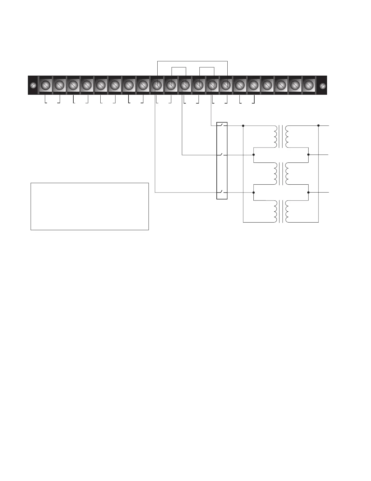
TB2
•
12
•
34
•
56
•
78
•
910
•
11 12
•
13 14
•
15 16
•
17 18
•
19
20
I(1-2)
I(3-4) I(5-6) V(1-2)
V(3-4) V(5-6) V1
I(SEF)
CØ
BØ
AØ
DISCONNECT
SWITCHES
(customer-supplied)
ote:N Terminal Block positions TB2-9 and
TB2-14 are factory-jumpered together.
Terminal Block positions TB2-10 and
TB2-11 are factory-jumpered together.
Terminal Block positions TB2-12 and
TB2-13 are factory-jumpered together.
Figure12. Customer connections to TB2, 120 VAC Delta Connection
The AC voltage inputs for both source or load side accept a
voltage input of 120 VAC nominal. For single-phase source
side AC voltage inputs, connections to AØ, BØ, or CØ
areacceptable.
The following are not functional for single phase AC
voltage input:
Directional Protection
Single-Phase Voltage Protection
Three-Phase Metering
Sync Check
 Loading...


