TABLE 5-3. Function Codes (continued)
Func.
Code
Level 1
Main Menu
Level 2
Sub-Menu
Level 3
Parameter
Security Level Factory
Setting
Key Entry Limit
Read Edit Reset Low High
64
Features Communications 064 Com Port #1
2179 Remote Adrs
1
0 2 NA 1 0 2046
• This is the control SCADA 2179 Remote Address for Com1/Com3.
• Each control on the system can be uniquely addressed by the SCADA RTU or other communications device. For 2179, the
options include:
• 0–2046 = Unique device address range. Controls with addresses in this range uniquely respond when the particular
address is sent.
• All controls on the system listen and change as commanded, with no response, if a message is sent to address 2047.
• The control SCADA address for Com Port #1 is entered at FC 64.
• For 2179, the High Entry Limit is 2046.
65 Features Communications 065 Com Port #1
Handshake Mode
RTR without CTS
0 2 NA RTR
without
CTS
NA NA
• FC 65 allows the user to select the appropriate method for control-to-SCADA message interaction (handshake mode) on Com1/
Com3.
• The transmit/receive handshaking mode allows adaptability to different types of communication system interfaces with the
control. Options include:
• RTS without CTS - Request to Send (RTS) without Clear to Send (CTS) support
• RTS with CTS - Request to Send (RTS) with Clear to Send (CTS) support
• RTR without CTS- Ready to Receive (RTR) without Clear to Send (CTS) support
• RTR with CTS - Ready to Receive (RTR) with Clear to Send (CTS) support
• See FC 66 and FC 67 for programming of the Transmit Enable Delay and Transmit Disable Delay settings.
66 Features Communications 066 Com Port #1
Tx Enable Delay
0 mSec
0 2 NA 0 0 1000
• When the control is set for transmit control handshaking, the user may require a delay (in milliseconds) on Com1/Com3
between the time when the transmit enable is enabled to when data is transmitted.
• Example: If the transmit enable were used as a keying device for a transmitter or modem, a “warm-up“ period may be
necessary before data can be transmitted.
• For more information, refer to the Advanced Control Features: Communications section of this manual.
67 Features Communications 067 Com Port #1
Tx Disable Delay
0 mSec
0 2 NA 0 0 1000
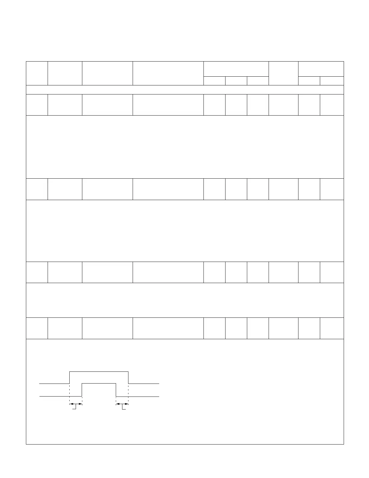
• When the control is set for transmit control handshaking, the user may require a delay (in milliseconds) on Com1/Com3
between the time when the data transmission is terminated and the transmit enable signal is disabled.
• See Figure 5-4.
FC 66
Transmit
Enable
Delay On
Transmit
Enable Off
Transmit
Enable On
Data
Message
FC 67
Transmit
Enable
Delay Off
Figure 5.4. Data transmission from the CL-6 control to the communication system for handshaking applications.
54
CL-6 SERIES CONTROL INSTALLATION, OPERATION, AND MAINTENANCE INSTRUCTIONS MN225016EN January 2016
 Loading...


