Do you have a question about the Eaton Aeroquip Rynglok Fitting System and is the answer not in the manual?
Procedures for cutting tubes using appropriate cutting tools, ensuring reasonable squareness.
Deburring tube ends (OD and ID) to prevent fitting damage and Foreign Object Damage (FOD).
Deburring painted tube ends, managing paint removal, and repainting exposed tubing.
Applying positioning and inspection marks on tube ends using methods like stamping or laser etching.
Positioning the marking gauge on the tube end to ensure accurate placement of marks.
Using the positioning mark to align the unswaged fitting ring over the tube marks for correct insertion.
Installing end fittings with the tube end bottomed into the fitting, with limited positioning allowance.
Selecting the correct size and pressure class assembly tool by matching fitting ring color to tool jaw color.
Connecting the hydraulic hose from the pump to the assembly tool's nipple.
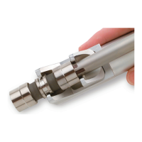
Aligning the assembly tool with the fitting, ensuring the ring is in the movable jaw and the tool is bottomed.
Applying hydraulic pressure to advance the fitting ring and complete the assembly process.
Ensuring the correct pressure level (8000-8500 psig) is applied for proper swaging.
Verifying proper ring advancement using the inspection gauge.
Ensuring the fitting edge is touching or over the insertion inspection marks for correct tube depth.
Understanding how insertion allowance is shared between tube ends in union fittings.
Adhering to guidelines for fittings other than unions with positive stops to ensure proper inspection.
Repairing tubing defects using a single union fitting, provided defect length is within specified limits.
Making a single cut through the center of the defect for single union repair.
Preferred method for single union repair: completely removing the defect section.
Repairing defects exceeding limits by cutting out the section and installing two Rynglok unions.
Using the reversed tool for installations near bulkheads or structural members where standard tools won't fit.
Using special reversed tools for reducer/expander fittings with different body sizes.
Using swage bridge attachments with size -20 and -24 standard/reversed swage tools.
Specifies tube cut dimensions for proper installation of Female Arcseal fittings.
Specifies tube cut dimensions for proper installation of Female Flareless fittings.
Specifies tube cut dimensions for proper installation of Female Flared fittings.
| Brand | Eaton |
|---|---|
| Model | Aeroquip Rynglok Fitting System |
| Category | Power Tool |
| Language | English |