4 EATON Aerospace Group TF100-67A March 2013
Rynglok Fitting System Installation Guide
2.0 Fitting Installation
2.1 Positioning Mark
The installer must use this positioning mark to position the edge of
the unswaged fitting “ring” over the marks as shown in Figure 3.
The length of the positioning mark is the amount of positioning toler-
ance allowed. The edge of the fitting “ring” may be anywhere along
the length of the positioning mark.
2.1.1 End Fittings
In general, end fittings are designed to have the tube end bottomed
into the fitting, and do not have as much positioning allowance. See
Figure 5. Even with this condition, the tube end should be marked
for inspection purposes to verify that the tube was inserted to at
least the minimum insertion depth. Refer to section 7.0 when install-
ing fittings of this type.
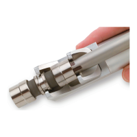
Figure 4
End fitting tube positioning. Note: Tube is bottomed into fitting.
Figure 3
Fitting position for tube insertion
 Loading...