3
Instruction Booklet IB48050
Effective September 2012
Instructions for installation,
operation, and maintenance of the
AMPGARD 15 kV, 300A vacuum starter
EATON CORPORATION www.eaton.com
Ratings
Table 1. Starter Ratings
Description
Utilization Voltage Rating
10,000 to 11,000V 12,400 to 13,800V
Interrupting rating E1 (unfused) 5 kA 5 kA
E2 (fused) 950 MVA at 11,000V 1190 MVA at 13,800V
E2 (fused) 63 kA 63 kA
Continuous current 300A 300A
Induction motor 6000 hp 7500 hp
Synchronous motor (0.8 PF) 6000 hp 7500 hp
Synchronous motor (1.0 PF) 6750 hp 8500 hp
Transformer 5400 kVA at 11 kV 6800 kVA at 13.8 kV
BIL 75 kV 95 kV (with arrestors)
Table 2. SL Contactor Ratings
Description Rating
Maximum voltage 15,000V
Maximum interrupting current
(three operations)
5000A
Rated current 300A enclosed/300A open
IEC make-break capability
AC3—Make
AC3—Break
3200A
2560A
Short time current
30 seconds
1 second
8.75 milliseconds
1920A
4800A
25 kA peak
Mechanical life 1 million operations
Electrical life 100,000 operations
Dielectric strength (60 Hz) 36 kV (1 minute)
Closing time 80 milliseconds
Opening time 130 to 330 milliseconds (selectable)
Weight 95 lbs (43 kg)
Arcing time 12 milliseconds (3/4 cycle) or less
Pickup voltage 80% rated coil voltage
Description Rating
Dropout voltage 60% rated coil voltage
Control voltages
AC
DC
110/120/220/240V (50/60 Hz)
125V
Control circuit burden (rated volt)
Closing
Holding
2600 VA
80 VA
Auxiliary contact ratings
Voltage (maximum)
Continuous current
Making capacity (AC)
Making capacity (DC)
Breaking capacity (AC)
Breaking capacity (DC)
600V
10A
7200 VA
200 VA
720 VA
200 VA
Latch (when specified)
Mechanical life
Trip voltages (DC)
Trip voltages (AC)
Tripping voltage
Tripping burden
24 Vdc
48 and 96 Vdc
110 and 220 Vac
250,000 operations
24/48/96V
110/220V (50/60 Hz)
80% rated coil voltage
1200 VA
400 VA
500 VA
Ratings are based on full voltage starting of standard motors
with locked rotor current equal to 6-times full load current and
an acceleration time of 10 seconds. The starter may be supplied
with a definite purpose rating of up to 300A depending on the
type of starting (reduced voltage autotransformer for example),
locked rotor current, and acceleration time. Consult the factory
for more information.
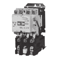
Starters are supplied with bolt-in main fuses. Contactors have
stab-in connections to the starter cell.
The flow of current through a starter with bolted fuses and a
stab-in contactor can be described as follows: The line finger
assembly mounted at the back of the enclosure serves to connect
the isolation switch moving stabs to the controller line terminals
when the switch is closed. Power flows from the switch moving
stabs through two flexible shunts to the upper fuse mountings.
The fuses are connected to the lower fuse mountings that contain
the line-side stab connections to the line finger assemblies for the
main contactor. With the main contactor energized, power flows
through the contactor’s vacuum interrupters to the contactor load
fingers, which are engaged on to the controller load-side stabs.
Medium voltage cables connect the load-side stabs to the motor
load connections. The contactor is held in place by a set of rails
mounted in the lower part of the cell. For full-voltage starters, the
motor load connections are mounted to the left of the main fuses
in the rear of the compartment, facing forward. For reduced voltage
starters, the motor load connections are mounted in the left rear
of the reduced voltage structure. Current transformers are typically
mounted just below the motor load connections.


 To Next Page