EasyManua.ls Logo

Eaton A200 - User Manual

Eaton A200
6 pages
Print Icon
To Next Page IconTo Next Page
Loading...
Effective May 2011
Supersedes April 1988
Instruction Leaflet IL15465
Instructions for A200 Size 3 or 4, 3 Pole
Motor Controller
THE CONTACTORS
The A200 motor controller, when wired as shown in Figures
5 and 6, will operate as a full voltage starter and will give
protection against overload, but not against short-circuit currents,
when wired and provided with overload relay (OLR) heaters as
listed in heater selection tables or when used with any means of
inherent protection activated by motor temperature.
The controller should be protected against short circuits by
providing branch circuit protection not to exceed the maximum
protective device ratings listed in Table I.
This industrial type control is designed to be installed, oper-
ated, and maintained by adequately trained workmen. These
instructions do not cover all details, variations, or combinations of
the equipment, its storage, delivery, installation, check out, safe
operation, or maintenance. Care must be exercised to comply with
local, state, and national regulations, as well as safety practices,
for this class of equipment.
AUXILIARY CONTACTS - TYPE J
A J20 with two normally-open poles is supplied mounted in the
upper left hand corner recess of the contactor. One pole is used
as the holding circuit auxiliary.

Other manuals for Eaton A200

Question and Answer IconNeed help?

Do you have a question about the Eaton A200 and is the answer not in the manual?

Summary

Instructions for A200 Size 3 or 4, 3 Pole Motor Controller

The Contactors

Explains the function and protection capabilities of the A200 motor controller.

Controller Ratings

Lists horsepower ratings for three-phase motors at various voltages and frequencies.

Power Circuit Terminals

Specifies wire sizes for power circuit terminals for NEMA sizes 3 and 4.

Auxiliary Contacts - Type J

Details the Type J auxiliary contacts, including mounting and function.

Type J Contact Ratings

Provides contact ratings for Type J auxiliary contacts across various voltages.

Type A Overload Relay

Explains the Type A overload relay, its features, and reset operation.

Heaters

Details the need for external heaters and their selection based on motor current.

Coil

Explains the A200 motor controller coil and its wiring for dual voltage operation.

Short-Circuit Withstand Ratings

Details the short-circuit withstand capabilities for Size 3 and Size 4 controllers.

Maintenance

Provides essential steps for safely performing maintenance on the motor controller.

Overview

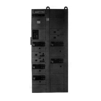
The Eaton A200 Size 3 or 4, 3 Pole Motor Controller is an industrial control device designed for full voltage starting of motors, providing protection against overload but not short-circuit currents. It requires external branch circuit protection. This controller is intended for installation, operation, and maintenance by adequately trained personnel, adhering to local, state, and national regulations, as well as safety practices.

Function Description:

The A200 motor controller operates as a full voltage starter. It provides overload protection when wired with overload relay (OLR) heaters selected from the provided tables or when used with inherent motor temperature protection. Short-circuit protection must be provided externally, with maximum protective device ratings specified in Table I.

Important Technical Specifications:

Controller Ratings:

  • NEMA Size 3:
    • Three Phase Horsepower at 60 Hertz: 25 HP (200V), 30 HP (230V), 50 HP (380V), 50 HP (460/575V)
  • NEMA Size 4:
    • Three Phase Horsepower at 60 Hertz: 40 HP (200V), 50 HP (230V), 75 HP (380V), 100 HP (460/575V)

Power Circuit Terminals:

  • NEMA Size 3: Wire Size #12-2/0 AWG
  • NEMA Size 4: Wire Size #12-4/0 AWG
  • Wire with copper conductors only.

Auxiliary Contacts - Type J:

  • A J20 with two normally-open poles is supplied, mounted in the upper left-hand corner recess of the contactor. One pole is used as the holding circuit auxiliary.
  • Maximum of four auxiliary units can be installed.
  • Contact Types: 2 Normally Closed (J02), 2 Normally Open (J20), 1 Normally Open and 1 Normally Closed (J11), 1 Normally Open and 1 Normally Closed, DB* (J1C).
  • Ratings (A600, Q600):
    • Voltage (VAC):
      • 120-600V: 10A Continuous, 7200VA Make, 720VA Break
      • 72-120V: 10A Continuous, 60A Make, 720VA Break
      • 28-72V: 10A Continuous, 60A Make, 10A Break
    • Voltage (VDC):
      • 301-600V: 2.5A Continuous, 0.1A Make, 0.1A Break
      • 28-300V: 2.5A Continuous, 69VA Make, 69VA Break
    • *DB - Delayed Break

Overload Relay Control Contact Ratings:

  • Type A (24-120 AC Volts): 20A Make, 2A Break (Normally Closed); 5A Make, 0.5A Break (Normally Open)
  • Type A (120-600 AC Volts): 2400VA Make, 240VA Break (Normally Closed); 600VA Make, 60VA Break (Normally Open)
  • Type B (24-120 AC Volts): 30A Make, 3A Break (Normally Closed); 30A Make, 3A Break (Normally Open)
  • Type B (1260-600 AC Volts): 3600VA Make, 360VA Break (Normally Closed); 3600VA Make, 360VA Break (Normally Open)

AC Coil Data (Size 3 and 4, Typical Values):

  • Inrush VA: 625
  • Sealed VA: 50
  • Sealed Watts: 18
  • Pickup Time (in Milliseconds): 33-41
  • Dropout Time (in Milliseconds): 12-16

Short-Circuit Withstand Ratings (Size 3):

  • Class H Fuse (200A): 5,000A (600V)
  • Class J Fuse (200A): 100,000A (600V)
  • Class R Fuse (200A): 100,000A (600V)
  • Class T Fuse (200A): 100,000A (600V)
  • Magnetic Only Type CB (100A Marked HMCP): 100,000A (480V), 50,000A (600V)
  • Thermal/Mag. Type CB (150A): 65,000A (480V), 25,000A (600V), 100,000A (480V), 35,000A (600V)
  • Mag. Only Type CB+CL (100A HMCP+Current Limiter):* 100,000A (600V)
  • Thermal/Mag. Type CLB (150A): 150,000A (480V)

Short-Circuit Withstand Ratings (Size 4):

  • Class H Fuse (400A): 10,000A (600V)
  • Class J Fuse (400A): 100,000A (600V)
  • Class R Fuse (400A): 100,000A (600V)
  • Class T Fuse (400A): 100,000A (600V)
  • Magnetic Only Type CB (150A Marked HMCP): 100,000A (480V), 50,000A (600V)
  • Thermal/Mag. Type CB (250A): 65,000A (480V), 25,000A (600V), 100,000A (480V), 35,000A (600V)
  • Mag. Only Type CB+CL (150A HMCP+Current Limiter): 100,000A (600V)
  • Thermal/Mag. Type CB+CL (250A): 200,000A (600V)
  • Thermal/Mag. Type CLB (250A): 150,000A (480V)

Usage Features:

Overload Relay Types:

  • Type A (Non-ambient Compensated): Unmarked, red reset rod. Bimetal actuated with trip indicator, ±15% rating adjustment, and normally closed control contact. Can be set for hand or automatic reset.
  • Type B (Ambient Compensated): Marked "ambient compensated," gray reset rod. Bimetal actuated with trip indicator, and normally closed control contact. An optional isolated normally open control circuit is available. A yellow dot appears when tripped. Resetting returns the indicator to its normal concealed position.
  • Reset Operation (Type A): Position the reset plate away from the panel for "hand" reset. Loosen the locking screw, move the plate toward the panel, and retighten for "auto" reset. Automatic reset is not recommended for 2-wire control circuits where automatic motor starting may be hazardous.

Heater Selection:

  • Heaters are not included and must be ordered separately.
  • Heaters should be installed with clean connecting surfaces and securely attached.
  • Trip rating in a 40°C ambient is 125% of the minimum full load current (Table I).
  • Relay trips within 20 seconds or less at 600% of its trip rating.
  • Selection based on motor nameplate full load current and service factor.
  • For service factor 1.15-1.25, select from heater application table.
  • For service factor 1.0, no service factor shown, or 115% protection desired, select one size smaller heater.
  • When motor and OLR are in different ambients or using non-compensated OLRs, adjust motor current: decrease 1% for each °C motor ambient exceeds controller ambient; increase 1% for each °C controller ambient exceeds motor ambient.
  • WARNING: If a current element burns out, the complete overload relay must be replaced to maintain fire and shock protection.

Coil Types:

  • Available with single or dual voltage coils.
  • Dual Voltage Coils: Normally wired for high voltage. Can be changed to low voltage by removing and reconnecting jumpers (Figure 4).

Control Circuit Fusing:

  • Minimum wire size in control circuit: #16 AWG.
  • Suggested fuse size: 10 AMP.
  • If using a control transformer, select fuse size per the National Electrical Code.
  • Fuse block kits (F56, FKR) are available to meet NEC requirements for common control fusing.

Maintenance Features:

Inspecting Contacts:

  1. Loosen the two arc box assembly screws (7) located above and below the nameplate.
  2. Remove the arc box (8).
  3. Contacts (5) are visible.
  4. Retighten screws per Table VII.

Replacing Contacts:

  1. After removing the arc box, compress the overtravel spring (12).
  2. Remove the moving contact (5) from the crossbar (6).
  3. Remove retaining screws (11) and lift out stationary contact carriers (14).
  4. To replace, reverse the procedure, ensuring stationary contacts are secure (Table VII), moving contacts are free to move, overtravel springs are seated, and the crossbar moves freely.
  5. Silver cadmium oxide contact buttons require no dressing or lubricant.
  6. Important: Replace all contacts and springs as a group to avoid misalignment.

Replacing The Coil:

  1. Loosen the assembly screws (10) located to the immediate left and right of the arc box.
  2. Remove connector straps to the overload relay.
  3. Pull the loosened upper base structure (9) forward.
  4. Pull the coil (1) from the upper base.
  5. Plug in a new coil.
  6. Replace the upper base structure and check auxiliary contacts for secureness.
  7. Tighten assembly screws and connector straps screws per Table VII.

Magnet - Armature Assembly:

  • Self-alignment and permanent air gap features make replacement unnecessary.
  • Mating pole face surfaces should be kept clean.
  • Arcbox must be in place when controller interrupts a circuit.
  • Cover Screw (2): 18-20
  • Coil Wire Connector (2): 8-9
  • Stationary Contact Screw (6): 18-20
  • Main Power Connector (6): 90-100
  • Overload Relay Connecting Screws (3): 45-50
  • Overload Heater Fastening Screws (6): 45-50

Eaton A200 Specifications

General IconGeneral
BrandEaton
ModelA200
CategoryController
LanguageEnglish

Related product manuals