Do you have a question about the Eaton S811 and is the answer not in the manual?
Checklist for control terminal block operation, including jumper settings and 24VDC power.
Checklist for power wiring, ensuring correct voltage and phase sequence.
Recommendations for kick start time and torque for generator power operation.
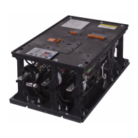
The S811 is a soft starter designed for controlling the starting and stopping of motors in various industrial applications. It aims to provide a smooth and controlled acceleration and deceleration of the motor, thereby reducing mechanical stress on the system and minimizing current surges during startup. This controlled operation helps to extend the lifespan of the motor and associated equipment, as well as reduce energy consumption.
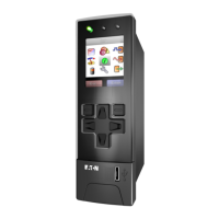
The device features a Digital Interface Module (DIM) with a display that provides real-time status information. This includes the operational status (e.g., ONLN, SS, OXFDO1, H STOP), line currents for L1, L2, and L3, and the current in Amps for each line. The display also includes soft key functions and predefined keys for navigation and control. The soft keys allow users to access various menus and settings, while predefined keys like JOG, RESET, and H->A offer quick access to common operations. An ESC key is also provided for navigating back through menus.
For control and power, the S811 requires a 24 Vdc power supply. The wiring diagram illustrates the connections for incoming lines (L1/1, L2/3, L3/5) and the 24 Vdc power supply. It also shows connections for external control inputs such as E-Stop, Stop, Start, Jog, and Reset. These inputs are designed to operate with 24 Vdc signals. The device includes internal contacts (H, Ready, Fault) that can be used for signaling the operational status to external systems, such as optional 24 Vdc pilot lights. A jumper between +24V and terminal 3 is indicated for specific control configurations. The S811 is designed to interface with a motor, providing controlled power to it.
The installation guide provides a checklist for wiring and control through the control terminal block. This includes ensuring a jumper is installed between terminals P and 1 for two-wire control, verifying that the 24V power supply meets minimum requirements (55 watts steady-state, 240 watts inrush for 180 ms, 30 Vdc maximum), and confirming that the control power wire for the positive and negative terminals is 14 AWG or larger and less than 100 feet in length. It also specifies that 24V should be supplied to pin 3 on the control terminal block if controlling through these terminals.
For power wiring, the checklist emphasizes applying 24 Vdc control voltage to terminal P and ensuring the phase sequence is correct (ABC) to prevent a phase reversal trip. If an output isolation contactor is used, it must not open until the soft starter stops to prevent a low current trip. After completing these steps, line power and 24 Vdc control voltage should be applied, followed by initiating a start signal to energize the motor.
The S811 offers various settings for typical applications, categorized under a Configuration Menu and Protections Menu. The Configuration Menu includes parameters such as Overload trip FLA, Overload trip class, Start method, Soft start time, Initial torque, Kick start time, Kick start torque, Soft stop time, Pump stop time, and Start control. These parameters can be adjusted for different motor types and applications, including pumps, fans, unloaded conveyors, rock crushers, saws, and compressors. For instance, the "Start method" can be set to "voltage ramp" or "pump control," and "Start control" can be "Level" or "Edge."
The Protections Menu includes settings for Phase imbalance fault, Phase sequence, and Motor rated voltage. The "Phase imbalance fault" can be enabled or disabled, and the "Phase sequence" is typically set to ABC. The "Motor rated voltage" can be set to the rated system voltage. Specific notes highlight that the starter must be ordered with pumping software for certain applications, and that a value of one (current limit start) may be selected for some applications, but longer starting times and constant loads should be observed. It also mentions that a two-second stop time is required for ammonia compressor applications. Customers operating on ungrounded or high-resistance grounded systems may need to adjust the severity and duration of imbalance protection to prevent false trips due to phase angle shifts.
The FLA setting calculation is a crucial aspect of configuring the S811. It is determined by multiplying the motor nameplate full load amperes (FLA) by a service factor multiplier (SF). For example, a 100A, 1.15 service factor motor would have an FLA setting of 115 (100 x 1.15). The device supports a range of FLA values, which are categorized by frame size (N, R, T, U, V) and corresponding catalog numbers. This allows users to select the appropriate S811 model based on their motor's FLA requirements.
For special applications, particularly when operating on generator power, the S811 can be optimized by setting the kick start time to 2 seconds and the kick start torque to half the value of the initial torque setting. This creates a step loading effect on the generator, which helps the governor regulate the power demand more effectively when starting larger motors.
Maintenance features are not explicitly detailed in the provided document, but the focus on proper wiring, configuration, and protection settings implies that correct initial setup is key to reliable operation and minimizing the need for maintenance. The troubleshooting section directs users to the S811 User Manual (MN03902002E) for additional setting details and to EatonCare for technical questions, suggesting that detailed troubleshooting and maintenance procedures would be found in the comprehensive user manual. The device's design, with its various protection features like phase imbalance fault and phase reversal trip, contributes to its overall reliability and helps prevent damage that might otherwise necessitate maintenance. The ability to adjust parameters for specific applications also allows for fine-tuning to ensure optimal performance and longevity of the motor system.
| Category | Controller |
|---|---|
| Input Voltage | 24 VDC |
| Output Voltage | 24 VDC |
| Protection Class | IP20 |
| Product Name | Eaton S811 |
| Number of Inputs | 8 |


 Loading...