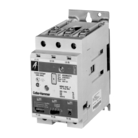
Do you have a question about the Eaton Cutler-Hammer Easy-Start ES Series and is the answer not in the manual?
| Category | Controller |
|---|---|
| Input Voltage | 200-480 VAC |
| Input Frequency | 50/60 Hz |
| Output Voltage | 200-480 VAC |
| Enclosure Type | NEMA 1 |
| Protection Features | Overload, Phase Loss |
| Dimensions | Varies by model |
| Weight | Varies by model |
Explains the meaning of safety alert symbols and statements like Danger, Warning, and Caution.
Provides specific safety statements related to installation, operation, and troubleshooting.
Outlines the manual's purpose, content, and how to use it for successful installation.
Provides guidelines to consider before installing the Easy-Start ES drive, covering description and wiring.
Details the Easy-Start ES unit, its features, block diagram, and system schematics.
Explains the coding system used for Easy-Start ES model numbers, including ratings and enclosures.
Discusses factors like installation, ambient temperature, altitude, and multi-motor operation.
Covers essential electrical connections, transformer wiring, and wiring practices for installation.
Presents a block diagram illustrating the functional components of the Easy-Start ES.
Shows system schematics for Hevi-Duty and Cutler-Hammer transformer connections.
Details the functions of terminal block TB1 on the logic board for various inputs and outputs.
Provides a graph showing derating factors for the Easy-Start ES at different altitudes.
Illustrates common control inputs like start/stop pushbuttons and selector switches.
Shows power connection diagrams with options for Hevi-Duty and Cutler-Hammer transformers.
Presents dimension and installation drawings for various Easy-Start ES enclosure types.
Lists current ratings, voltage, output stage, ambient temperature, and semiconductor details.
Explains operation modes (Voltage Ramp, Current Ramp) and key adjustments like DIP switches.
Details DIP switch settings for calibrating current ratings and ampere settings.
Describes voltage plugs and logic board jumpers required for proper operation based on voltage.
Lists available options for Easy-Start ES, including operator devices, control devices, and transformers.
Details available plug-in option kits and specifications for circuit breakers.
Explains special function option boards (E, S, J, U) and the daughter board (D).
Provides application notes and examples for specific options like Extended Start Time and Smooth-Stop.
Presents current vs. time rating charts for NEMA-1 and NEMA-12 enclosures for options.
Shows schematic diagrams for various options like Extended Start Time and Smooth-Stop.
Illustrates DIP switch settings and trip time curves for Jam and Underload options.
Provides component layout diagrams for various option boards (E, S, J, U, D).
Shows dimensions for logic board, daughter board, and cover board assemblies for options.
Provides systematic checks for problems like motor not rotating or not reaching full speed.
Details procedures for testing SCRs, gates, and logic board outputs for diagnosing faults.
Lists replacement parts, including logic boards, SCRs, transformers, and option boards.


