2
Instruction Leaflet IL15465
Effective May 2011
A200 Size 3 or 4, 3 Pole Motor Controller
EATON CORPORATION www.eaton.com
AUXILIARY CONTACTS - TYPE J (Cont.)
A maximum of four auxiliary units can be installed with ter-
minals either in line or in a right angle relationship to the power
poles. Auxiliary contacts mount by means of a spring clip and
retainer screw. To remove the unit rotate the retainer screw several
times (counterclockwise) and then slide the auxiliary contact unit
out of the recess.
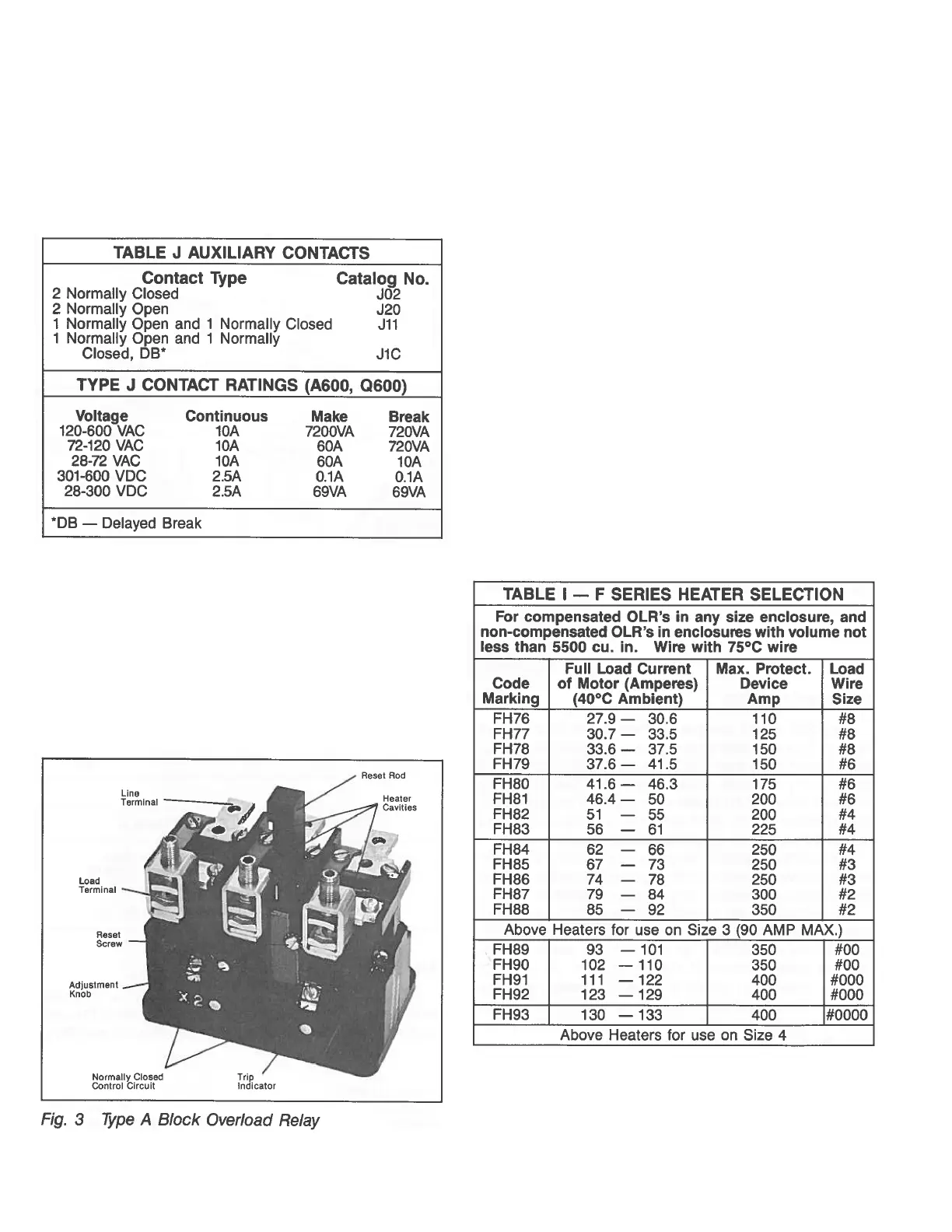
TYPE A OVERLOAD RELAY (See Figure 3)
The A200 motor controller can be equipped with a Type A block
type non-ambient compensated overload relay (unmarked and
with red reset rod) or with a block type temperature compensated
overload relay (marked “ambient compensated” and with gray
reset rod). The relay is of the bimetal actuated type equipped with
trip indicator, trip adjustment covering ± 15% of rating and a
normally closed control contact. It may be operated with either
hand or automatic reset.
Reset operation is determined by the position of the plate on
the load side of the overload base. Position the reset plate away
from the panel to set the “hand” position. Loosen the locking
screw, move the reset plate toward the panel, and retighten the
screw to set the “auto” position.
Automatic reset should not be used with 2-wire control circuits
where automatic starting of the motor may be hazardous
AUXILIARY CONTACTS - TYPE J (Cont.)
This A200 motor controller is usually equipped with a Type B
block type ambient compensated overload relay (with gray reset
rod). The controller can also be supplied with a non-ambient
compensated overload relay (with red reset rod). The relay is of
the bimetal actuated type equipped with a normally closed
control contact. An optional isolated normally open control circuit
is available for field mounting. When the overload relay trips, a
yellow dot will appear flush with the molded surface below the
reset rod. Resetting the relay returns this indicator to its normal
concealed position.
HEATERS
Heaters are not included with the motor controller and must
be ordered separately per the heater selection table and the
information listed below. When installing heaters be sure that
connecting surfaces are clean and heaters are attached securely
to the relay in the proper location with the screws provided. The
trip rating of a heater in a 40°C ambient is 125% of the minimum
full load current shown in Table 1. When tested at 600 percent of
its trip rating, the relay will trip in 20 seconds or less.
WARNING: To provide continued protection against fire and
shock hazard, the complete overload relay must be replaced if
burnout of a current element occurs. See Table II.