Instruction Bulletin IB00414001Y
Effective January 2015
Complete Home Surge Protection
Installation and Operating Guide
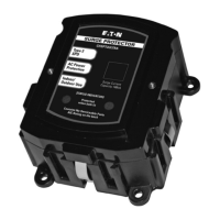
Thank you for purchasing an Eaton
®
Complete Home Surge
Protective (CHSP) device. This product forms part of the CHSP
modular surge protection system, consisting of:
•
The CHSPT2SURGE or CHSPT2ULTRA AC module, designed to
protect residential electrical and electronic loads from voltage
transients and surge disturbances on your AC power line and
intended for both indoor and outdoor usage.
•
The CHSPCABLE module, designed to protect coaxial cables
providing service for televisions, satellite TV and other coaxial
connected equipment from electrical transients and surge
disturbances and intended for indoor use only. Outdoor
installations require a separately purchased outdoor enclosure
(accessory: CHSP3RTELCABLE).
The Eaton system is designed for maximum installation flexibility
in newly constructed or existing homes. For example, in new
construction, when coaxial cables are routed close to the electrical
panel, the CHSP modules can be joined together using the unique
quick-connect feature found on each protection module, for a neatly
configured surge protection system (see Figures 8, 9, and 10).
These instructions do not cover all details, variations, or
combinations of the equipment, its storage, delivery, installation,
checkout, safe operation, or maintenance. If you require further
information regarding a particular application or installation that is not
covered in this manual, please contact Eaton’s Technical Resource
Center at 1-877-ETN-CARE, option 2, then option 1.
Safety Precautions
A licensed / qualified electrician must complete all instructions
described in this manual in accordance with the U.S. National
Electrical Code, state and local codes, or other applicable country
codes. All electrical codes supersede these instructions.
WARNING! SHOCK HAZARDS
Improper installation can cause death, injury and /or
equipment damage. Follow all warning and cautions.Completely
read and understand the information in this instruction manual
before attempting to install or operate this equipment.
Improper wiring could cause death, injury, and / or equipment
damage. Only licensed / qualified electricians who are trained in the
installation and service of electrical devices are to install and service
this equipment.
Use appropriate safety precautions and equipment for arc
flash protection.
During normal operation, hazardous voltages are present inside
the SPD.
When servicing the SPD, follow all safe work practices to avoid
electrical shock.
CAUTION
Do not perform a high-pot test with the SPD connected to the
electrical system. Failure to disconnect the SPD during a high-pot
test will result in damage to the SPD.
IMPORTANT
•
Choose a mounting location for the CHSP that provides the
shortest and straightest possible wiring (lead length) from the
CHSP to the electrical system connections. Excessive lead length
and sharp bends will degrade the performance.
•
When using conduit, avoid using 90º elbows and keep the conduit
run as short and straight as possible.
Mounting
The CHSPT2SURGE/CHSPT2ULTRA is designed to be connected to
the top, bottom or sides of your electrical loadcenter
, see Figure
1, or alternatively it can be surface mounted or flush mounted on
the wall adjacent to the loadcenter.
Definition: The term loadcenter refers to the electrical panel
(or breaker panel) in your home.
To install this device you need:
•
Four self-tapping screws — #8 x 3/4-inch (1.9 cm)
(surface mount only — supplied with purchase).
•
Slot and Phillips screwdriver.
•
Hammer, wire cutter and wire stripper.
•
For finished wall applications, you should purchase the Flush
Mount lid (accessory: CHSPFMKIT)
Pre-Installation
•
The loadcenter must be properly grounded and meet local, nation-
al (NEC
®
) or Canadian (CEC) electrical code approved practices.
•
The CHSP can be used with any manufacturer’s loadcenter
(breaker panel).
Circuit Breaker Installation
1. Turn OFF power to the loadcenter.
2. Remove loadcenter cover.
3. Verify power has been disconnected with a portable
voltage meter.
4. Locate a dedicated unused, or install a new 2-pole circuit breaker
in an available space closest to the location where the CHSP is
to be installed. A dedicated 2-pole 15 ampere circuit breaker is
recommended for use with CHSP devices, but use a 2-pole 50
ampere circuit breaker to achieve the full published ratings of the
CHSPT2ULTRA device. (The connecting wires do not carry supply
current. Instead, they carry only short-duration currents that are
associated with a transient event.)
5. Move circuit breaker handle to the OFF position.
Indoor Installation
Panel Mount (Figures 1 and 2)
6. Remove 1/2-inch (1.25 cm) knockout located closest to the
2-pole breaker installed in Step 4.
7. Remove lock nut from the threaded nipple and feed the CHSP
wires through the knockout. Secure the CHSP in its final position
by reattaching lock nut and tighten firmly using hammer and
screwdriver or suitable wrench. Continue with final installation
Step 11.
Surface Mount
8. Using the supplied four (4) self-tapping screws, mount the
CHSP on a suitable surface through the four mounting holes.
The wires should be protected using rigid or flexible Electrical
Metal Tubing. Continue with final installation Step 11.
Table 1. Recommended Dedicated Circuit Breaker to Achieve
Published Rating
Catalog Number Pole Rating
CHSPT2SURGE 2-Pole 15 ampere
CHSPT2ULTRA 2-Pole 50 ampere
2
EATON CORPORATION www.eaton.com