Do you have a question about the Eaton CM52 and is the answer not in the manual?
Inspect units for damage upon arrival and file claims within 24 hours if damage is apparent.
Details on lifting the breaker and enclosure, including required spreader use.
Guidelines for storing submersible units with doors closed and shipping covers.
Describes the CM52 as an air circuit breaker with a relay for voltage/current response.
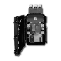
Details the main components: Cassette Frame, Circuit Breaker Unit, Arc Chutes, CTs, Operating Mechanism, Control Module.
Steps for removing the drawout unit from its housing, including opening the door and levering the breaker.
Details the CM52 submersible enclosure's construction and features like external handle.
Describes the mechanical anti-close interlock feature and its function.
Steps for installing the network protector onto the transformer flange with provided hardware.
Overview of CM52 circuit breakers, draw out and fixed configurations, and controls.
Details the rigid frame housing construction and the 3-piece construction approach.
Describes the individually enclosed current carrying pole unit and its components.
Explains the composition of primary moving contacts, including fingers and the 'Heel'.
Describes the primary stationary contact as a combination of a conductive pad and an arc runner.
Details electrical operation, including spring charging, manual/automatic closing, and trip/lockout features.
Explains arc chambers for insulation and the process for removing arc chutes.
Details how to remove arc chutes using a captive bolt and sliding the frame rearward.
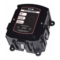
Describes the four-part tripping system: Relay, CT, Trip Actuator, and IDM.
Details optional auxiliary switches for remote indication and their layout.
Lists replaceable parts for the CM52 breaker, including motor assembly, relays, and actuators.
Explains the electrical interlock assembly and its purpose in preventing unsafe closing operations.
Step-by-step guide for changing the handle position from right to left side of the tank.
Lists hardware included in the Handle Change Bag for modifying handle position.
Details the hardware contents for the 800-2000A CM52 model.
Details the hardware contents for the 2250-3000A CM52 model.
Details the hardware contents for the 3500-4500A CM52 model.
Provides steps for cleaning, inspecting, and verifying status flags and LEDs during maintenance.
Instructions for inspecting sight glass, door gasket, and checking for loose items at the enclosure bottom.
Procedure for removing the breaker for detailed maintenance inspection.
Details inspection of wiring, arc chutes, charging mechanism, and contact wear.
Steps for electrical testing, including breaker insertion, test position, and phasing block checks.
Instructions for checking zero voltage and connecting test kit leads to the test switch.
Steps to follow after successful tests, including handle position and door closure.
| Mounting | Unit Mount |
|---|---|
| Communication | No |
| Poles | 2 |
| Trip Unit | Thermal-Magnetic |
| Standards | IEC |