ix
Instruction Booklet IB 52-01-TE
Effective October 2010
Instructions for the Eaton Type CM52
Network Protectors 800 to 4500 Amperes
EATON CORPORATION www.eaton.com
ix IB -52-01-TE
Effective 11/05/08 (super cedes 11/19/03) IB 52-01-TE
INTRODUCTION
PURPOSE
This instruction book is expressly intended to
describe the installation, operation and
maintenance of the Type CM52 network
protectors. Should any item not be sufficiently
covered by these instructions and additional
information is required, contact your local
Cutler-Hammer offi ce.
Information regarding operation, maintenance,
and testing of network relays is contained in
Instruction Book 35-581B.
For application information, consult your nearest
Cutler-Hammer sales offi ce, or see appropriat e
ANSI standards.
CAUTION
IT IS NOT SAFE TO OPERATE THE CM52
NETWORK PROTECTORS UNLESS THEY
ARE INSTALLED IN A SUITABLE METAL
ENCLOSURE OF ADEQ UATE STRENGTH
TO WITHSTAND THE EFFECTS OF HIGH
CURRENT SHORT CIRCUIT FORCES; OR
BODILY INJURY AND/OR PROPERTY
DAMAGE COULD RESULT.
The need to provide el ectrical power at the
utilization voltage – without increasing
equipment size – has resulted in a shi ft from
125/216 – volt to 277/480 – volt systems. With
this trend toward the high er voltag e, a ch ange in
operation and maintenance procedures is
required, becaus e of the di fference in arcing
characteristics at 480-volts as compared to those
125/216 volts. For example, while an arc in a
216-volt system is normally self-extinguishing,
an arc in a 480-volt system will usually burn
until an extinguishing device interrupts it or until
it totally consumes the arcing material.
Cutler-Hammer CM52 Netwo rk Protectors are
designed to assure service continuity in 125/216
and 277/480 volt Y connected secondary
network systems. These systems, in either
distributed grid or spot network form, are
commonly used in such areas of high load
density as metropolitan and suburban business
districts.
When a fault on a primary system (cable or
network trans fo rmer) occu rs, the CM52 Network
Protectors will open to isolate the fault from the
network system. Loss of the feed er will not
result in service outage to any load on the
secondary network. The other primary feeders
will carry the load until the faulted feed er can be
brought back to service.
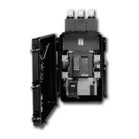
CM52 Network Protectors consist basically of an
air circuit break er, a breaker op eration
mechanism, network relays and control
equipment. Units are available in both
weatherproof and subm ersible enclosure, for
either separate or trans former throat mounting.
CM52 Network Protectors have a drawout
design with positive safety interlocks that
provide protection for personnel ag ainst contact
with energized components while disconnecting
the unit for test or mainten ance. All the main
current carrying and mechanical operating
components are located behind a “ dead-front”
cover that prevents tools or hands from being
inserted into an energized protector. The draw
out unit is operated by a hand-cranked levering
system, which cannot be engaged unless the
circuit breaker is open; and it cannot be
disengaged unl ess the draw out unit is either
fully disconnect ed or fully connected.
Modular construction facilitates field
maintenance and/or replacement of parts of the
draw out unit.
A spring close operating mechanism in the
network protectors prevents partial closures. The
CM52 spring-close mechanism will not permit a
closing motion of the contacts to start until the
closing springs are fully charged.
Externally mounted, silver-sand fuses are
provided to interrupt fault current by
disconnecting the protector from the network bus
in case the network protector would fail to trip.
As an additional option internal copper link, or
lead-alloy fuses can be fitted into a CM52
enclosure .
A low-energy, direct-trip actuator provides a
mechanical force to trip the circuit breaker.


 To Next Page