3
Instruction Leaflet IL29C204I
Eective October 2011
Installation Instructions for Motor Operator for
3- and 4-Pole ND, NB, NC, MD, MA, MC Type
Circuit Breakers and Molded Case Switches
EATON CORPORATION www.eaton.com
WARNING
BEFORE MOUNTING A MOTOR OPERATOR ON A
CIRCUIT BREAKER INSTALLED IN AN ELECTRICAL
SYSTEM, MAKE SURE THE CIRCUIT BREAKER
IS
SWITCHED TO THE
OFF
POSITION AND THAT
THERE
IS
NO VOLTAGE PRESENT WHERE WORK
IS
TO BE PERFORMED. SPECIAL ATTENTION SHOULD
BE PAID TO REVERSE FEED APPLICATIONS TO
ENSURE NO VOLTAGE
IS
PRESENT. THE VOLTAGES
IN ENERGIZED EQUIPMENT CAN CAUSE DEATH
OR
SEVERE PERSONAL INJURY.
CAUTION
ENERGIZING THE MOTOR OPERATOR WHEN IT
IS
AGE IT. ENSURE THAT THE MOTOR OPERATOR
IS
SECURELY MOUNTED TO A CIRCUIT BREAKER
BEFORE OPERATING ELECTRICALLY.
NOT MOUNTED TO A CIRCUIT BREAKER MAY DAM
-
Note: When the motor operator is mounted to the cir
-
cuit breaker, the circuit breaker nameplate is not visi
-
ble. Before mounting the motor operator, make sure
the circuit breaker nameplate information is recorded
for future reference.
A
blank nameplate is supplied
for this purpose. The nameplate should be placed on
the top side of the motor operator.
To
install the electrical operator perform the following
steps:
2
-
1.
2
-
2.
2
-
3.
2
-
4.
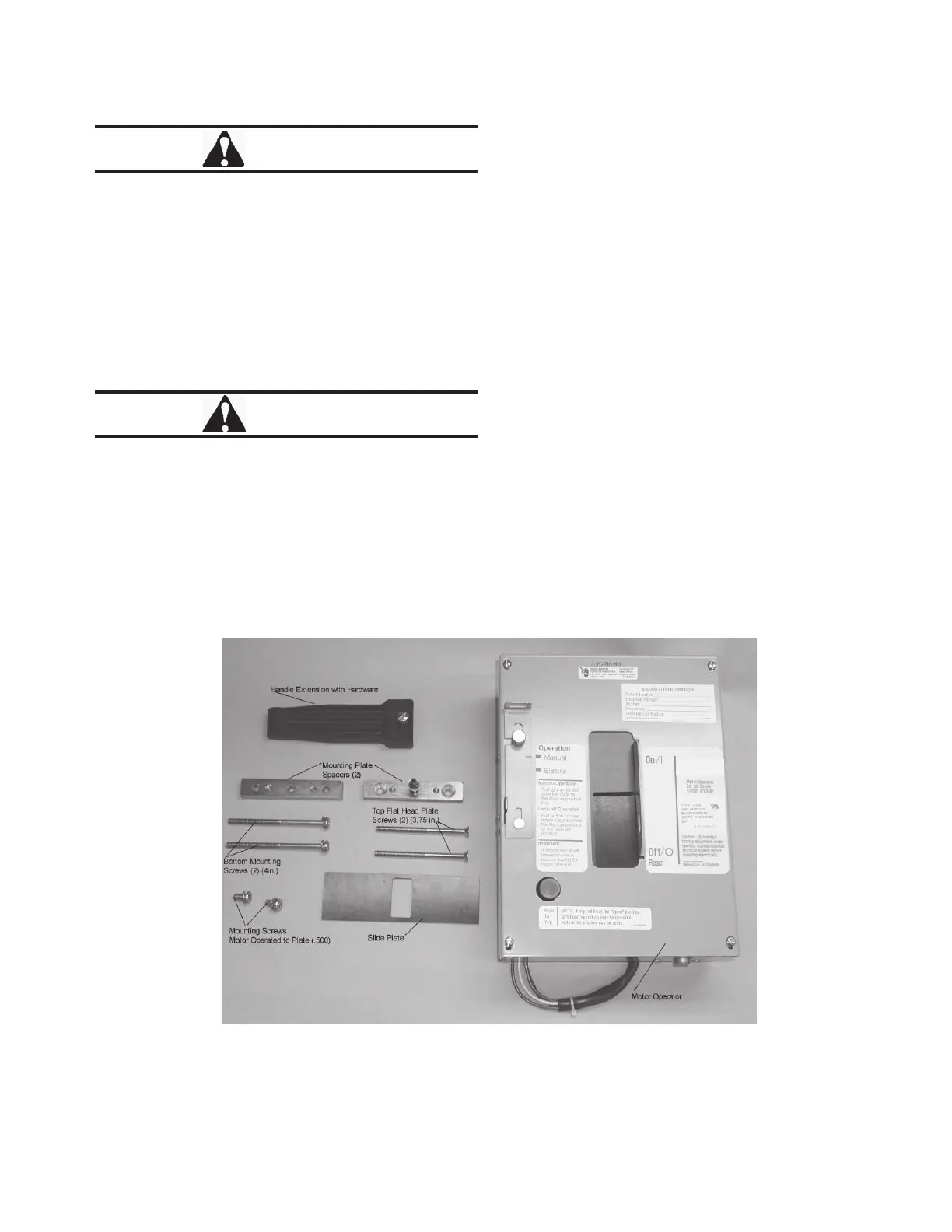
Remove motor operator from packing. Inspect it for
completeness (Fig. 2
-
1). Check the motor operator
nameplate to make sure that the rating agrees w
ith
the installation requirements; and make sure that
mounting hardware is included.
Install circuit breaker handle extension using nuts
and screws supplied. (See Fig. 2
-
3.)
Assemble top mounting plate (spacer) with 3.75
-
in.
flat head screws supplied (Figs. 2
-
1, 2
-
3, 4
-
2).
Motor operator frame is to mount to this top plate
motor operator to the circuit breaker with screws
Fig. 2-1
Motor Operator Kit
using two .500
-
in. pan head screws.
Trip breaker to the
"
TRIP
"
eht tnuoM .noitisop