4
Instruction Leaflet IL29C204I
Eective October 2011
Installation Instructions for Motor Operator for
3- and 4-Pole ND, NB, NC, MD, MA, MC Type
Circuit Breakers and Molded Case Switches
EATON CORPORATION www.eaton.com
,
.
Whits
d
-
-
DC
LEGEND
-
On
Switch
-
Switch
52a
-
Switch
-
Breaker Auxiliary
Switch
DIAGRAM
SHOWS
THE CIRCUIT
AND
MOTOR
OPERATOR
IN
‘OFF’ POSITION.
Fig.
2
-
2.
Motor Operator Wiring Diagram
The Head
of
the
Screw
Towards
“ O N ”
Direction
For tighting breaker cable boflom terminals
use
the
following steps:
1.
Remove the motor operator cover
2.
Loosen
two
4
in. pan head mounting screws
3.
Remove bottom mounting plate spacer
4.
Remove bottom terminal cover
Terminal
Block
Wire Connector
Terminal Screws
Wire Leads
Fig. Terminal Block and Wire Leads
supplied. Put the bottom mounting plate (spacer)
between the motor operator and the breaker
(Figs. 2
-
3 (lt.03)). The roll pin must be in the
base slot and the push nut inside the operator. Use
two 4
-
in. pan head screws. The handle extension
must be between the rollers of the bracket assem
-
bly, and the motor towards the line end of the
breaker (Figs. 2
-
3, 4
-
1).
2
-
5.
2
-
6.
2
-
7.
2
-
8.
The motor operator is equipped with a “PUSH
-
TO
-
TRIP” feature. Turn circuit breaker “ON”. Press the
“PUSH
-
TO
-
TRIP” button to verify that the breaker
trips. Reset breaker and turn “ON” again. Replace
the cover and cover screws, check the “PUSH
-
TO
-
TR
I
P” again
.
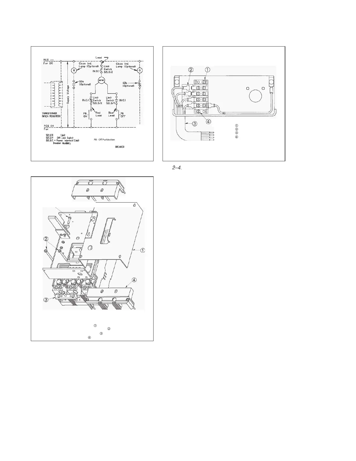
The motor operator is equipped with a terminal
block and 30
-
in. long wire leads. If it is desirable to
change wire leads, just pull out the wire connector,
and connect the new wire leads to the screws or
tabs of the terminal block. (See Fig. 2
-
4 page 3.)
If motor operator is used for
NB,
NC, or MD, MA,
MC type circuit breakers and molded case switches
the mounting screws must be changed to .190 x
3.375, .190 x 3.625, or .190-32 x 2.25, .190-32 x
1.75 pan head screw with lock washer.
To connect the power and control wiring, refer to
Fig. 2
-
2, page 3.
Fig.
2
-
3.
Terminal Tightening Instructions
P B - O n P u s h b u t t o n
52b
}
Momentary Contacts