2
Installation and User manual for the
conventional range of fire panels
EATON www.eaton.com
Technical Data PR000-00-513-05
Effective January 2018
General
Installation
Please read the following instructions before installing and wiring
the fire alarm panel.
This range of panels is EN54 parts 2 and 4 certified and have been
designed to comply with BS5839 part 1:2002 installations.
The panels have two optional features:
FIRE ALARM DEVICES: (EN54 part 2 clause 7.8)
TEST CONDITION: (EN54 part 2 clause 10.0)
In common with all electrical equipment the panel should be
installed in a clean, dry, well ventilated area, not in direct sunlight
and avoiding cold areas where possible. Note, temperatures in
excess of 40°C will affect the panel operation. The panel should be
located away from any potential hazard, in a position where it is
readily accessible to authorised staff and the fire services.
Ideally on the perimeter of a building near a permanent entrance.
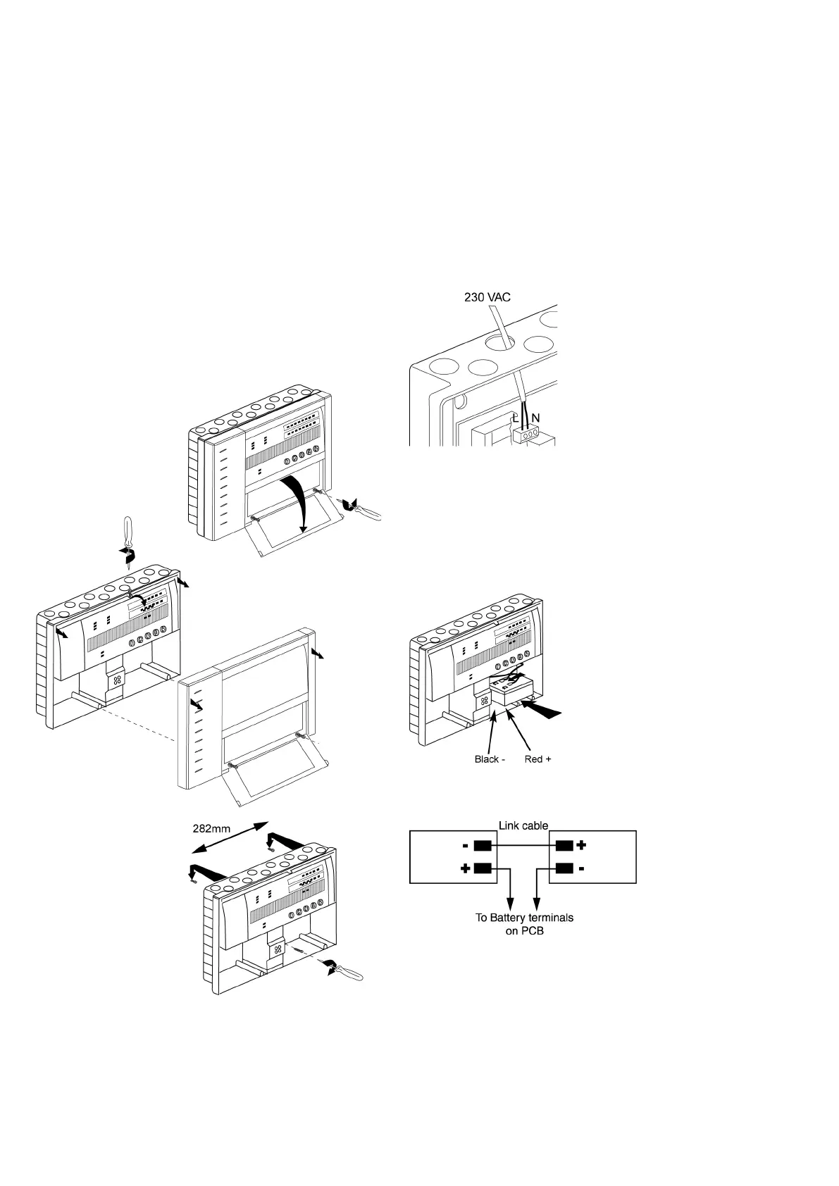
Figure 1. Panel installation
Mount the panel, using pre drilled screw positions, to the wall.
This will prevent any possible brick dust contamination of the
panel internal circuitry.
Fit a 20mm gland to all cable entry points in use.
Wiring
Mains power supply
The mains supply should be exclusive to the fire alarm as detailed
in BS5839 part 1. It is recommended that a double pole fused spur
unit is used and marked “FIRE ALARM DO NOT SWITCH OFF”,
this should be for the sole use of the fire alarm.
Within the panel, the mains supply should be isolated from the
zone and alarm line wiring and should be connected to the termi-
nal block marked MAINS.
Figure 2. Mains power connection
Battery connection
The 2 & 4 zone panel requires a single battery (supplied)
*Note: For -NB variants, purchase batteries seperately
2 and 4 zone panels: 1x12v 3.2Ah
Connect the red battery wire to the red battery terminal (+).
Connect the black battery wire to the black battery terminal (-).
Figure 3. Battery Connection location
Figure 4.
Battery Connection schematic
 Loading...