2
Explosionsgeschützte
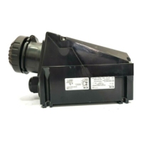
Steuergeräte GHG 418
Inhalt: Contents: Contenu:
Explosion-protected
control units GHG 418
Boites de commande GHG 418
pour atmosphères explosives
Inhalt ........................... ...................... 2
Maßbilder .............. ........... ................ 3
Anschlussbilder ............. ............ ....... 4
1 Technische Angaben ....... ............ ..... 3
1.1 Komplette Steuergeräte .... ........... .... 3
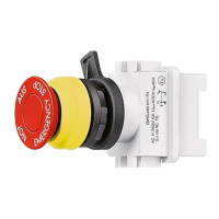
1.2 Drucktaster + Schalter ........ ............ . 4
1.3 Signallampe ..................... ........... ...... 4
1.4 Potentiometer ................ .......... ........ 4
2 Legende......... .............................. ..... 5
2.1 Sicherheitshinweise ......... ........... ..... 5
3 Normenkonformität ........ ........... ....... 5
4 Verwendungsbereich ... ............ ........ 5
5 Verwendung/Eigenschaften .............. 5
6 Installation ................ .......... .............. 6
6.1 Montage .................... ........... ............ 6
6.2 Öffnen des Gerätes/
Elektrischer Anschluss ...................... 7
6.3 Kabel- und Leitungseinführung;
Verschlussstopfen....................... ...... 7
6.4 Schließen des Gerätes ..... ........... .... 7
6.5 Inbetriebnahme ............. ........... ........ 7
7 Instandhaltung / Wartung ... ............ .. 7
8 Reparatur / Instandsetzung/
Änderungen ....... ........................... .... 7
9 Entsorgung / Wiederverwertung ...... . 7
Konformitätserklärung
separat beigelegt
Contents ........ ........... ........................ 2
Dimensional drawings ............ .......... 8
Contact arrangement ............ ........... 9
1 Technical Data ....................... ........... 8
1.1 Complete control units ......... ........... . 8
1.2 Push- button and switch ...... ............ 9
1.3 Signal lamp ........................... ........... . 9
1.4 Potentiometer ....................... .......... . 9
2 Principles................ .......................... 10
2.1 Safety instructions ................ ........... 10
3 Conformity with standards ... ........... 10
4 Field of application ................ .......... 10
5 Application/ Properties ......... ........... 10
6 Installation ............................ ........... 11
6.1 Mounting .............................. ......... .. 11
6.2 Opening apparatus /
Electrical connection ............ ........... 12
6.3 Cable entry (KLE);
blanking plug ........................ ........... 12
6.4 Closing apparatus ................ ............12
6.5 Putting into operation ........... ........... 12
7 Maintenance/Servicing ......... ........... 12
8 Repairs/Modifications .......... ............12
9 Disposal/Recycling ............... ...........12
Declaration of conformity,
enclosed separately.
Contenu ..... ........... ............................ 2
Plans cotés ............ .......................... 13
Schéma des conexions ..... .............. 14
1 Caractéristiques techniques............. 13
1.1 Boites de commande complètes .... 13
1.2 Bouton-poussoir et interrupteur ...... 14
1.3 Lampe de signalisation .................... 14
1.4 Potentiomètre ....................... .......... 14
2 Légende ......... .................................15
2.1 Consignes de sécurité ......... ............15
3 Conformité avec les normes ........... 15
4 Domaine d’utilisation ............. .......... 15
5 Utilisation/Propriétés ............ ........... 15
6 Installation ............................ ........... 16
6.1 Montage ............................... ........... 16
6.2 Ouverture de la boîte /
Raccordement électrique ..... ........... 17
6.3 Entrées de câble (KLE)
bouchons de fermeture ........ ........... 17
6.4 Fermeture de la boîte /
Fermeture du couvercle ....... ...........17
6.5 Mise en service .................... ...........17
7 Maintien/Entretien ................. .......... 17
8 Réparation/Remise en état ............... 17
9 Évacuation des déchets/Recyclage .. 17
Déclaration de conformité,
jointe séparément.
 Loading...