1. Introduction i-on40 & i-onEX Range
Page 8
(The top line of the display may show the
installer’s name instead of “i-on160”.)
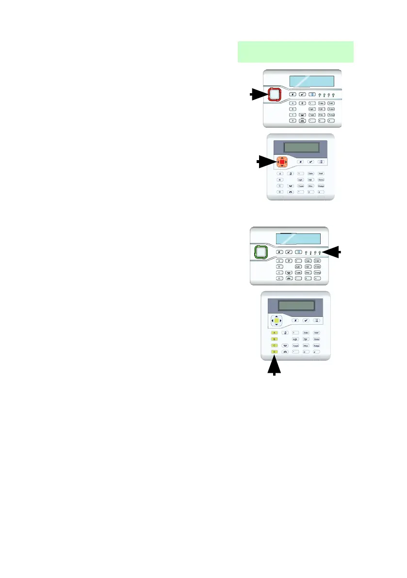
To draw your attention to special events the
navigation key glows red.
On an i-kp01 there are four LEDs to the right of
the programming keys. These LEDs show the
state of the ABCD keys. When the control unit
is delivered from the factory then:
In a part setting system these LEDs glow to
show you whether the system is set or
unset. The left hand or ‘A’ LED glows when
the system is full set, the other LEDs glow
when the system is in one of the part set
states.
In a partitioned system, the LEDs show the
status of partitions 1 to 4.
In a KEY-KX01, KEY-KP01 or KEY-KPZ01 the
LEDs are within the ABCD keys.
(See page 106 to find out what kind of control
unit your system has.)
Note that the installer can disable these LEDs in order to hide the state of
the system (to comply with EN50131). If you wish to change the function of
the ABCD keys (and consequently the LEDs) please consult the installer.
Detectors or Zones?
When talking about alarm systems, people tend to use the words
“detectors” and “zones” interchangeably. Most of the time this doesn’t
matter, but occasionally it can cause some confusion. In this book a
“detector” is a physical piece of equipment that signals some event. A
“zone” is how the keypad reports the location of the detector.

 Loading...


