2
Instructional Leaet IL019117EN
Effective July 2016
Installation guidelines for users of MagnumDS
Low-Voltage Rear-Access Switchgear Assemblies
for seismic applications
EATON www.eaton.com
2.00
(50.8)
Plan view
Floor steel
Floor steel
Floor steel
34.60
(877.8)
a
e
a
e
c
e
c
e
d
e
b
e
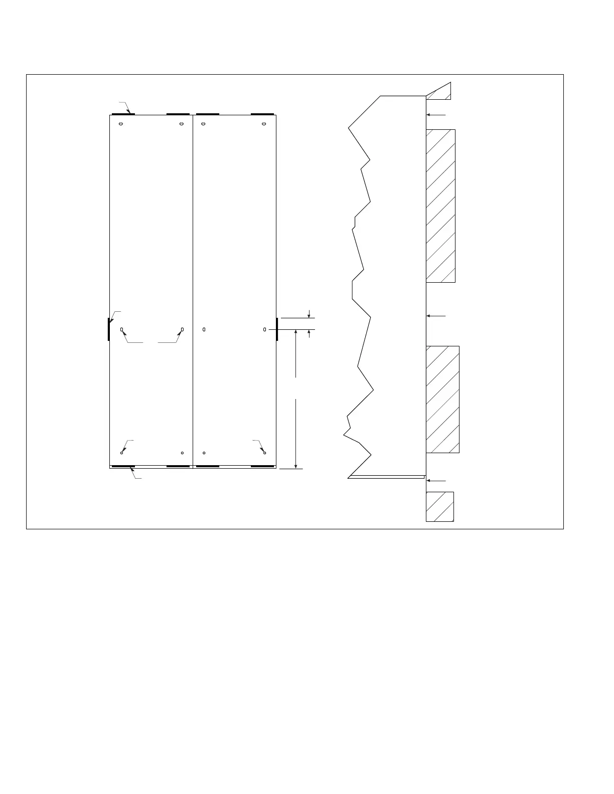
Figure 1. Welding of indoor structures to imbedded floor steel—rear-access MDS, MDN, MSB, and Series NRX
®
a
0.19 inches (4.8 mm) weld, 4.00 inches (101.6 mm) long at two places on front and rear of each section starting 0.50 inches (12.7 mm) from each edge of structure.
b
0.19 inches (4.8 mm) weld, 4.00 inches (101.6 mm) long on each end of line-up in area of bus compartment.
c
Internal bracket on each end of line-up to be plug welded to floor steel.
d
Floor mounting holes, in bus compartment, to be plug welded to floor steel.
e
For nuclear installations, weld per AWS D1.1, alternatively, welding procedures and personnel qualifications may be performed IAW ASME BPVC Section IX and
the inspections be performed IAW AWS D1.1, and/or D1.3 and/or D9.1.

 Loading...