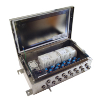
The MTL 937x-FB2-Px-SS Fieldbus Barrier System is a range of field-mounted wiring hubs designed for FOUNDATION™ fieldbus H1 instruments. These systems offer either six or twelve intrinsically safe spur connections from a single non-intrinsically safe trunk. The enclosures are constructed from stainless steel (SS), providing excellent chemical and moisture resistance, making them suitable for installation in Zone 1 or Zone 2 hazardous areas and corrosive environments.
Function Description:
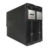
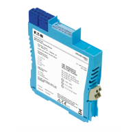
The core function of the 937x-FB2-Px-SS system is to convert a single non-intrinsically safe fieldbus trunk into multiple intrinsically safe spur connections. Each Fieldbus Barrier module (9377-FB-R) within the enclosure provides six intrinsically safe spurs. The system is bus-powered, eliminating the need for additional power supplies in the field, and is designed to operate with fieldbus host control systems, receiving power from IEC 61158-2 conforming supplies (e.g., MTL F800 or MTL 918x redundant power supplies).
The enclosures are supplied pre-drilled for all trunk and spur cable entries and can be fitted with Ex e certified nickel-plated brass blanking plugs and a breather. Short-circuit protection is built into each 9377-FB-R barrier module for outgoing spurs. Optional surge protection is available for individual spurs via FS32 Spur Surge protection modules and for the trunk via a 9376-SP Trunk Surge Protection module.
Important Technical Specifications:
- Enclosure Material: Stainless Steel (SS)
- Spur Connections: Available in 6-spur (9371-FB2-PS-SS, 9371-FB2-PC-SS) and 12-spur (9373-FB2-PS-SS, 9373-FB2-PC-SS) configurations.
- Hazardous Area Classification: Zone 1 or Zone 2 hazardous areas.
- Ingress Protection (IP) Rating: IP66 (to EN60529).
- Ambient Temperature Range: -40°C to +70°C (external to the enclosure).
- Cable Glands/Blanking Plugs: Must be ≥IP66 Ex eb tb certified with a minimum temperature range of -40°C to +75°C.
- Breather: Must be ≥IP66 Ex eb tb IECEx & ATEX certified with a minimum temperature range of -40°C to +75°C and IP rating (IP66) at least equal to that of the enclosure.
- Trunk Cable: Type 'A' fieldbus cable recommended.
- Spur Cable: Type 'A' fieldbus cable recommended.
- Terminal Blocks: Screw terminal connectors or spring clamp connectors (depending on model) suitable for cables from 0.5mm²/AWG 20 up to 2.5mm²/AWG 14.
- Grounding: M8 earth-grounding stud for protective local ground (4mm² cross-sectional area or better, tightened to 5Nm).
- Trunk Terminator: F93-XE module pre-installed, to be removed if the trunk segment continues to another node.
- Power LED (Green): ON indicates trunk power applied; OFF indicates insufficient or no trunk power (lights at >15.7V, may remain lit down to 13.0V).
- Spur LEDs:
- Green Steady: Channel powering spur, spur OK.
- Green Flashing*: Channel powering spur but spur open circuit.
- Red Steady: Short to shield on one or more spurs.
- Orange Flashing*: Spur short circuit, or spur in current limit state.
- (*Flashing occurs at approximately 2 pulses per second.)
- Nominal Weight (excluding surge protection modules):
- 9371-FB2-Px-SS: 5.7 kg
- 9373-FB2-Px-SS: 8.5 kg
- Certification: Baseefa 14ATEX0112X, IECEx BAS 14.0058X, Ex d e ib mb [ia Ga] IIC T4 Gb, Ex tb IIIC T80°C Db.
Usage Features:
- Mounting: Designed for vertical surface mounting with cable entry at the lowest point. Mounting holes are provided, and additional holes are not permitted as this would violate certification.
- Grounding Options: Supports two grounding methods:
- Option 1 (Default): Single point of grounding at the host, with trunk and spur shields interconnected at the barrier.
- Option 2: Trunk shield grounded at the host, and spur cable shields grounded at the barrier.
- Trunk Terminal Area (TTA): Protected by a transparent cover with a warning label to deter unauthorized access while powered.
- Cable Connections: Trunk cables are terminated in the TTA. Spur cables connect directly to barrier carrier terminals or through optional Spur Surge modules.
- Terminator Management: The F93-XE Fieldbus Terminator is pre-installed and should remain if the enclosure is the last on the trunk segment; otherwise, it should be removed.
- Live Work Capability: Individual 9377-FB-R Fieldbus Barrier modules, 9376-SP Trunk Surge modules, and FS32 Spur Surge modules, along with spur wiring, can be removed or disconnected while the trunk is still powered in a hazardous area without 'gas clearance,' provided normal 'permit to work' procedures are followed. All other wiring requires trunk power isolation or a gas clearance certificate.
Maintenance Features:
- Regular Checks: Recommended checks at least every two years (more frequently in harsh environments) include:
- Condition of all wire connections/terminations/screens.
- Security of all fixing and cover screws and blanking plugs.
- Clarity of the breather.
- Absence of damage or corrosion.
- Accumulated dust level not exceeding 5mm.
- Cleaning: The outer enclosure should be cleaned with a non-electrostatic generating cloth lightly moistened by a dilute mixture of detergent in water.
- Troubleshooting: LED indicators on the Fieldbus Barriers assist in fault identification for both power and individual spurs.
- Module Replacement: Modules (9377-FB-R, 9376-SP, FS32) are designed for easy fitting and removal. Care must be taken to ensure connection pins are not bent or damaged.
- Cable Adjustment: Procedures are provided for adjusting spur cable length when adding or removing Spur Surge modules to maintain proper connections and IP rating.
- Voltage Checks: During plant maintenance shutdowns or when the area is non-hazardous, the DC voltage on the fieldbus trunk can be checked (should be >16V) using a multimeter or FBT-6 fieldbus tester.
- Repair: The modules used in this product cannot be repaired by the user and must be replaced with equivalent certified products.
- EMC Immunity: Designed to operate reliably in industrial environments and comply with international standards for immunity to electromagnetic radiation. However, exposure to extreme levels of radiated electrical noise (e.g., from walkie-talkies or arc-welding) may cause damage, and power should be removed from the Fieldbus Barrier if such activity is unavoidable.