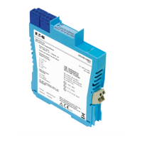
The MTL 9491-PS is an intrinsically safe power supply designed to provide power to MTL 9460-ET series Ethernet modules in hazardous areas. This module can be mounted in a safe area, Zone 2, or Division 2 hazardous area, offering flexibility in installation. It takes a 24V DC safe area / Zone 2 / Division 2 supply and produces an intrinsically safe, 12V DC nominal output.
Function Description
The primary function of the 9491-PS is to supply intrinsically safe power to 94xx Series Ethernet modules. It acts as an isolating power supply, ensuring that the power delivered to the hazardous area devices meets intrinsic safety requirements. The module offers two types of intrinsically safe outputs: Ex ia IIB Groups C, D, providing 200mA at 10.9V DC, and Ex ib IIB, providing 400mA at 11.8V DC. The choice between 'ia' and 'ib' outputs depends on the specific application, gas group, and zone classification, with the 'ib' output offering higher usable power where permitted. It is crucial to note that it is not permitted to connect to both 'ia' and 'ib' outputs on the same 9491-PS module.
For applications requiring multiple outputs for several Ethernet modules, a power distribution backplane is available to simplify the 24VDC input connection. Alternatively, multiple 9491-PS modules can be DIN-rail mounted with a "Powerbus" input for convenient power distribution. The module incorporates LED indicators for both input and output power, allowing for quick visual status checks. Internal current limiting and electronic auto-reset circuit breaker action are built-in to protect the module in case of short circuits or overloads, thereby minimizing power dissipation during faults and enhancing reliability.
The 9491-PS also supports a Power over Ethernet (PoEx) option, which is an adaptation of the IEEE 802.3af PoE standard. This allows two spare pairs in existing Cat5e cables to distribute power supplied by a 9466 Ethernet Switch (Power Sourcing Equipment - PSE) to connected devices (Powered Devices - PD). This adaptation is specifically designed for hazardous area use and does not imply conformance to the 802.3af PoE standard.
Usage Features
The 9491-PS offers versatile mounting options, including DIN-rail or backplane mounting, catering to different installation requirements.
For DIN-rail mounting, the modules can be clipped onto low-profile (7mm) or high-profile (15mm) type T35 DIN-rail. The blue signal plugs should face towards the hazardous-area wiring. When removing a module, a screwdriver blade can be inserted into the clip to gently lever it outwards, allowing the module to pivot off the rail. A maximum mounting pitch of 16.2mm per unit is recommended. The removable power plugs are fitted with screw clamp terminals, accommodating conductors between 14 and 24 AWG (1.6 and 0.5mm diameter). The input power plug slots into the socket at terminals 13 and 14 on the safe-area side of each module. For wiring, insulation should be trimmed back by 12mm, and conductors inserted according to terminal assignments, then screws tightened. If crimp ferrules are used, their metal tube length should be 10-12mm.
The "Powerbus" system simplifies power distribution for multiple DIN-rail mounted 9491-PS modules. A PB-8T power bus kit allows up to 8 modules to be linked to a standard 24V power supply. The bus consists of a chain of power plugs, available in different lengths. Users should ensure the bus length is correct for the number of modules. Surplus power plugs can be cut off from the tail end of the chain, leaving sufficient cable for future additions. Power plugs are inserted into the power terminals on the safe-area side of each module in sequence. The power supply source is connected to the tail end of the chain using insulation displacement connectors (Scotchloks) provided with the kits. It is important not to connect power buses in series to avoid excessive voltage drop or over-current. Surplus sections can be reused, provided cut ends are safely terminated.
For backplane mounting, the 9491-PS modules require minor modifications before installation: the DIN-rail mounting clip and the power supply plug on the side of the unit must be removed, and a small plastic plate supplied should cover the resulting hole in the module case. Backplanes accommodate 8 modules with 24V dc dual redundant power supplies. LEDs on the backplane indicate the operational status of the two supplies. A diode circuit ensures automatic switchover to the highest voltage supply if the primary source fails. Power supplies for backplanes can be interconnected in a ring configuration, which reduces wiring and allows individual backplanes to be taken out of service without affecting other backplanes, provided they are neighbors and do not leave any other backplanes without an active supply.
Accessories for both mounting methods include insulating mounting blocks, earth-rail brackets (straight and offset options), earth rails, tagging strips, tagging strip labels, DIN-rail module spacers, earth terminals, and tag holders. These accessories facilitate earthing, cable screen termination, and identification of individual units.
Maintenance Features
The design of the 9491-PS includes features that contribute to ease of maintenance. The removable power plugs simplify wiring and replacement of modules. Sufficient free cable should be allowed during installation to permit easy removal of plugs for future maintenance or replacement.
The internal current limiting and electronic auto-reset circuit breaker action protect the module from damage due to short circuits or overloads, which minimizes the need for manual intervention and improves overall reliability.
For backplane installations, the ring wiring configuration for multiple backplanes allows individual backplanes to be taken out of service without disrupting power to other modules, provided they are adjacent and an active supply is maintained. This modularity simplifies troubleshooting and replacement.
The module is designed for installation, operation, and maintenance by trained competent personnel in accordance with international, national, and local standard codes of practice and site regulations. Regular refresher training for personnel is recommended.
The product cannot be repaired by the user and must be replaced with an equivalent certified product if it becomes faulty. Access to the internal circuitry should not be made during operation.
Environmental considerations include an operating temperature range of 0°C to +70°C and a storage temperature range of -20°C to +70°C, with humidity between 5% and 95% RH (non-condensing). When mounted in a safe area, the local environment should be clean and free of dirt and dust. When mounted in a Zone 2 hazardous area, the module must be protected by a suitably certified enclosure with a minimum ingress protection rating of IP54.
Waste removal information emphasizes that the electronic equipment must not be treated as general waste and should be disposed of correctly to prevent negative environmental and health consequences. Detailed information on take-back and recycling can be obtained from the MTL product line.