10
INM9491 Rev 3
4 BACKPLANE MOUNTING METHOD
The alternative to DIN-rail mounting is to use a standard MTL backplane that accommodates 8 modules
with 24V dc dual redundant power supplies. In applications where a number of backplanes are installed,
the power supply can be interconnected. Optional earth-rail and tagging-strip kits are available for the
backplanes.
WARNING: If this module is to be connected to intrinsically safe apparatus, it must be installed,
operated and maintained only be trained competent personnel and in accordance with all
appropriate international, national and local standard codes of practice and site regulation and in
accordance with the instructions contained here.
4.1 Accessories
Accessories are available that enable the user to mount the backplanes. These include surface-mounting
kits, T-section and G-section DIN-rail mounting kits and end stops.
MOUNTING KITS ACCESSORIES
DIN-rail 19-inch Earth-rail Tagging Spare
Surface (T or G) rack kit strip kit fuse pack
SMS01 DMK01 – ERK08– TSK08 FUS08
4.2 Protection of equipment
When the power supply is mounted in a safe area ensure that the local environment is clean and
free of dirt and dust and note the ambient temperature considerations given in Section 5.
WARNING: When mounted in a Zone 2 hazardous area the module must be protected by a
suitably certified enclosure. See the Special Conditions for Safe Use provided in the ATEX Safety
Instructions at the end of this manual for further details of operation in Zone 2 hazardous areas.
4.3 Backplane mounting
See the table for details of the kits and accessories applicable to the mounting methods and Figure 4.1
for dimensions and mounting centres.
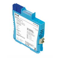
Note: Before mounting a 9491-PS on a backplane two minor modifications must be made.
1.
Remove the DIN-rail mounting clip by compressing the small spring inside the clip with a
screwdriver and then removing it; the clip may then be removed easily from its mounting.
2.
Remove the power supply plug located in the side of the unit, then fit the small plastic plate
supplied to cover the hole in the module case.
Figure 4.1:
CPS08 backplane
for 9491-PS
modules

 Loading...
