This document serves as an installation guide for the REC Series Rack, a robust enclosure designed to house and protect electronic equipment. The guide provides comprehensive instructions for the safe and efficient setup, configuration, and maintenance of the rack, ensuring optimal performance and longevity.
Function Description
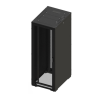
The REC Series Rack is a versatile enclosure system primarily designed for the secure housing of electronic devices and accessories in various environments, including data centers, server rooms, and industrial settings. It provides a structured and protected space for equipment, facilitating organization, cooling, and power management. The rack is available in different widths (600mm and 800mm) and heights (42U and 47U), accommodating a wide range of equipment sizes and configurations. Key components include an enclosure frame, vented door assembly options (single or double), side panels, and roof panels. The design emphasizes stability, load-bearing capacity, and ease of access for installation and maintenance.
Usage Features
- Load Capacity: The REC Series enclosure is engineered to support significant loads. It has a static equipment load capacity of 1100kg and a dynamic combined load of 200kg. This robust construction ensures that the rack can safely hold a substantial amount of electronic gear. However, it is crucial to note that the fitted casters are intended for transit only and should not be used to move the rack when the combined weight of the rack and equipment exceeds 200kg. For loads exceeding this dynamic limit, the leveling feet must be in contact with the floor to provide stable support.
- Stabilization: Before installing any roll-out type accessories, components, or electronic devices, the enclosure must be stabilized. This is achieved by adjusting the four leveling feet, ensuring they are in firm contact with the floor. For enclosures with casters, the leveling feet should be extended approximately 3mm off the floor to prevent tipping. This stabilization procedure is critical to prevent the enclosure from tipping over, especially when equipment is being installed or accessed.
- Equipment Loading Sequence: To maintain stability and prevent the enclosure from becoming top-heavy, the heaviest electronic devices and accessories should always be loaded into the bottom of the enclosure first. This practice helps to lower the center of gravity, enhancing overall stability.
- Roll-out Device Management: When using roll-out type electronic devices or accessories, it is imperative to extend only one device at a time from a stabilized enclosure. Users should never sit, stand, or climb on any extended roll-out device. Furthermore, roll-out components should not be extended from an enclosure rack that is supported solely by casters, as this can lead to tipping.
- Door Handing Switching: The REC Series Rack offers the flexibility to switch the door handing (left or right opening). This feature allows for customization based on the layout of the installation environment. The process involves removing hinge pins, relocating hinge sections to the opposite side of the frame, rotating the door 180 degrees, and then re-installing the hinge pins. Adjustments to the door lock, fixing plate, and locking rods are also required to complete the handing switch.
- Side Panel Installation and Removal: Side panels are designed for easy installation and removal, facilitating access to the interior of the rack for equipment setup and maintenance. Removal involves unlocking the panel with a key, tilting it to clear the upper flange, and then lifting it upwards to disengage from two locating pins. Reinstallation is the reverse process, aligning the bottom holes with the pins and then lowering and locking the panel.
- Rack Mount Adjustment: The rack mounting rails are adjustable to accommodate various equipment depths. To adjust, four bolts securing the rails are loosened using a 5mm Allen key (without removing them). The rails can then be slid to the desired location. Once positioned, ensuring the rails are vertical, the bolts are tightened with the Allen key.
- Aisle Containment: The REC Series Rack supports aisle containment solutions, available in 1200mm and 1800mm widths. These solutions help manage airflow and cooling efficiency within data center environments. End of aisle kits are ordered to suit the specific aisle width, and roof panels are ordered separately. The installation involves assembling frame uprights, cross beams, and top panels, followed by fitting hinges and doors. The doors are equipped with a mechanism that allows them to be opened from inside the aisle, enhancing safety and accessibility. Self-adhesive bump-stops are also fitted to the doors.
Maintenance Features
- Earth Bonding: A comprehensive earth bonding system is integrated into the REC Series enclosure to ensure electrical safety. A grounding kit is supplied, and the installer is responsible for grounding the enclosure to the building's electrical system. Additional grounding points are available for electronically bonding equipment to the rack's frame. The earth bonding instructions detail the fitting of main rack earth bonding points to corner gussets, door earth bonding to the bottom earth stud, and 19-inch rail earth bonding. These connections are secured with specific screws, washers, and nuts, tightened to specified torque values (e.g., 12Nm for main rack bonding, 6Nm for door bonding). This meticulous approach to grounding minimizes the risk of electrical hazards and ensures compliance with safety standards.
- Component Earth Continuity: The bolt-together method used for the rack frame construction inherently ensures earth continuity among the rack frame components. Factory-assembled elements such as the rack roof panel, infill roof plates, and base corner gussets are secured with fixings that guarantee they are earthed to the rack frame. This design simplifies maintenance by ensuring that core structural components are automatically grounded.
- Door and Panel Adjustments: The design allows for adjustments to door positions and panel gaps. By loosening the hinge fixing screws, the relative positions of the hinges can be altered, enabling the installer to achieve an optimal gap of approximately 3 to 4mm between the door and the frame. These hinge adjusting screws are accessible from the rear of the frame and doors (inside the aisle), making fine-tuning straightforward.
- Tool Requirements: The installation and maintenance procedures are designed to be performed with common tools, including 8mm and 10mm spanners (wrenches), 4mm and 5mm Allen keys, and a cross-head screwdriver. This standardization of tools simplifies the process for technicians.
- Safety Warnings and Guidelines: The manual emphasizes several safety warnings to protect personnel and equipment during installation and maintenance. These include recommendations for multiple people to assist with unpacking heavy components, ensuring all safety regulations are observed when lifting, and adhering to load limits. Warnings also cover the importance of stabilizing the enclosure, loading heaviest items at the bottom, and safely managing roll-out devices. The document also highlights the need for an uninterruptible safety earth ground and cautions against high leakage current, stressing the importance of grounding connections. These guidelines are crucial for preventing accidents and ensuring a safe working environment.