64
11 Modbus register map
PXR TRIP UNITS FOR POWER DEFENSE MOLDED CASE CIRCUIT BREAKERS MN012007EN March 2019 www.eaton.com
11.3.5 Block of registers
A block of registers can be established in trip unit to remap the data object registers of an
Eaton product. The block map of registers is stored in non-volatile memory.
Function code 16 is used to load the object assignments for the block of registers. The block
assignments are stored beginning at 401001/420481 (0x03E8/0x5000). Only the first data
object register address is assigned within the block of registers. For example, although data
object IA occupies register 0x1202 and 0x1203, only register 0x1202 is loaded into the block
of assignment registers. Verification of this block of assignment registers can be read from
trip unit with a function code 03 or 04 from these 401001/420481 (0x03E8/0x5000) registers.
Data pertaining to the objects configured in the block of assignment registers is mapped into
registers starting at 401201/420737 (0x 04B0/0x5100) and continuing in successive order for
each object assigned. The number of objects and their placement order in this data block of
registers is dependent on the configuration of the block of assignment registers. The total
number of data block of registers is limited to 100.
The data can be obtained from the data block of registers by a read function code 03 or
04. The address of the starting object must be aligned with a starting address of an object
within the data block of registers. The number of registers to obtain must align with an
ending address of an object within the data block of registers.
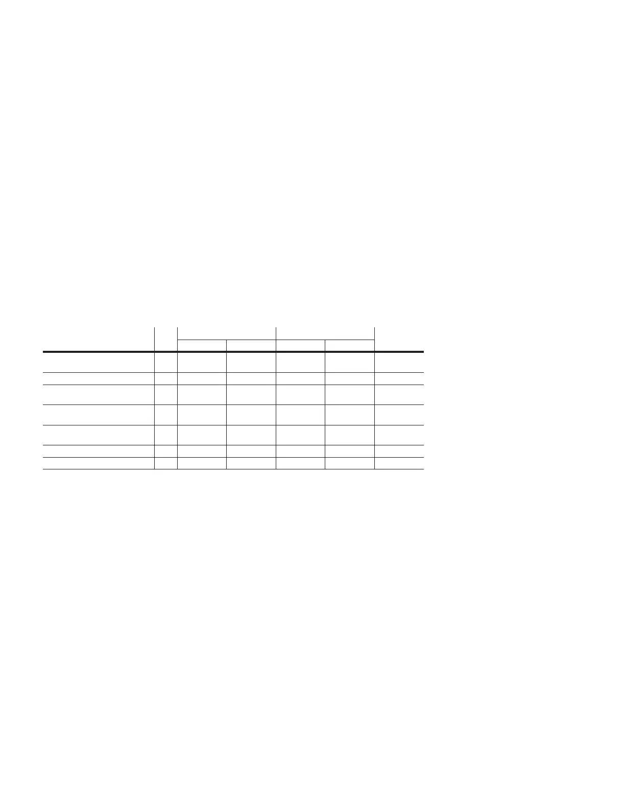
Configuration registers
Register definition R/W Modbus register number Modbus register address Number
Low High Low High
Mapped block of registers
configuration
R/W 401001 420481 0x03E8 0x5000 100
Mapped block of registers data R 401201 420737 0x04B0 0x5100 100* 2
Invalid object access
configuration
R/W 402001 425345 0x07D0 0x6300 1
Floating point data word order
configuration
R/W 402002 425346 0x07D1 0x6301 1
Fixed point data word order
configuration
R/W 402003 425347 0x07D2 0x6302 1
Remote control R/W 402901 425089 0x0B54 0x6200 3
Date and time register R/W 402921 0x0B68 8
Non-volatile Register 402001/425345(0x07D0/0x6300) is used to configure trip unit to respond to a group of data objects.
See 11.2.1 Communications protocol options.
To accommodate Modbus master that can only access to register 9999, some Eaton
registers initially assigned above 9999 have been assigned dual access, both at the origi-
nal register(to provide compatibility) and at a new register assignment below 9999. The
format is given as low/high register numbers followed by (low16/high16 Modbus register
addresses).
11.3.6 Remote control
A set of registers is reserved for trip unit remote control, starting from 42901/425089
through 42903/425091. These three registers should be written together with a “slave
action number” and its first complement using function code 16. The “slave action number”
and its function are listed in remote control data formats, their support being product
dependent.
If the “slave action number” and its first complement command is valid, trip unit will
execute the action. Once the command is successfully acknowledged by trip unit, it returns
a normal function code 16 response to Modbus master. Since it may take some time for
trip unit to take action, Modbus master may further determine if the product completed the
slave action function successfully after the normal response by interrogating the trip unit,
for example, by reading its status. If the “slave action number” and its first complement
command is invalid, trip unit returns exception code 03.

 Loading...