66
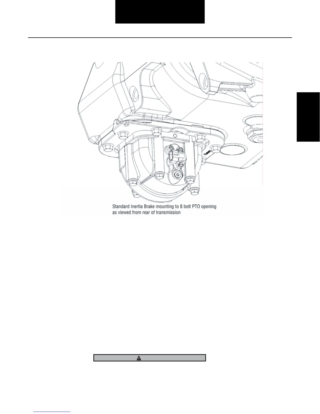
Inertia Brake
Inertia Brake
Installation
1. Clean and thoroughly dry all mating surfaces (including the gasket) prior to assembly.
Note: The transmission inertia brake
may be mounted to the 6-bolt PTO opening directly, or mounted utilizing a 6-bolt PTO Angle
Adapter to assist in aiding chassis clearance.
2. If a 6-bolt PTO Angle Adapter is required, install the angle adapter to the 6-bolt PTO opening following the
manufacturers instructions. See picture of 6-bolt
installation with angle adapter.
3. If the Inertia brake is installed directly
mounted to the 6-bolt opening, proper orientation must be followed as shown in
the “Final Check” section. A directly mounted Inertia Brake also requires a new lubrication hose, Eaton part
number 5588209.
4. Using the six (6)
3/8” mounting bolts, install the Inertia Brake and gasket, being careful to align the Inertia Brake gear
with the drive gear. Tighten mounting bolts to 40-45 lb-ft (54-61 Nm) using a cross pattern.
Note: When
mounted directly - orient the inertia brake housing with hose connection forward / electrical connection rearward as
shown in the “Final Check” section (same orientation as 8-bolt). When mounted to a 6-bolt PTO Angle Adapter - orient the
inertia brake housing with hose connection rearward / electrical connection forward as shown in the “Final Check”
section. Ensure gasket, inertia
brake, and mating mounting faces are assembled dry (no lubricant or grease).
The Inertia Brake is heavy. Be prepared to handle the weight of the Inertia Brake until the mounting bolts are installed.
 Loading...