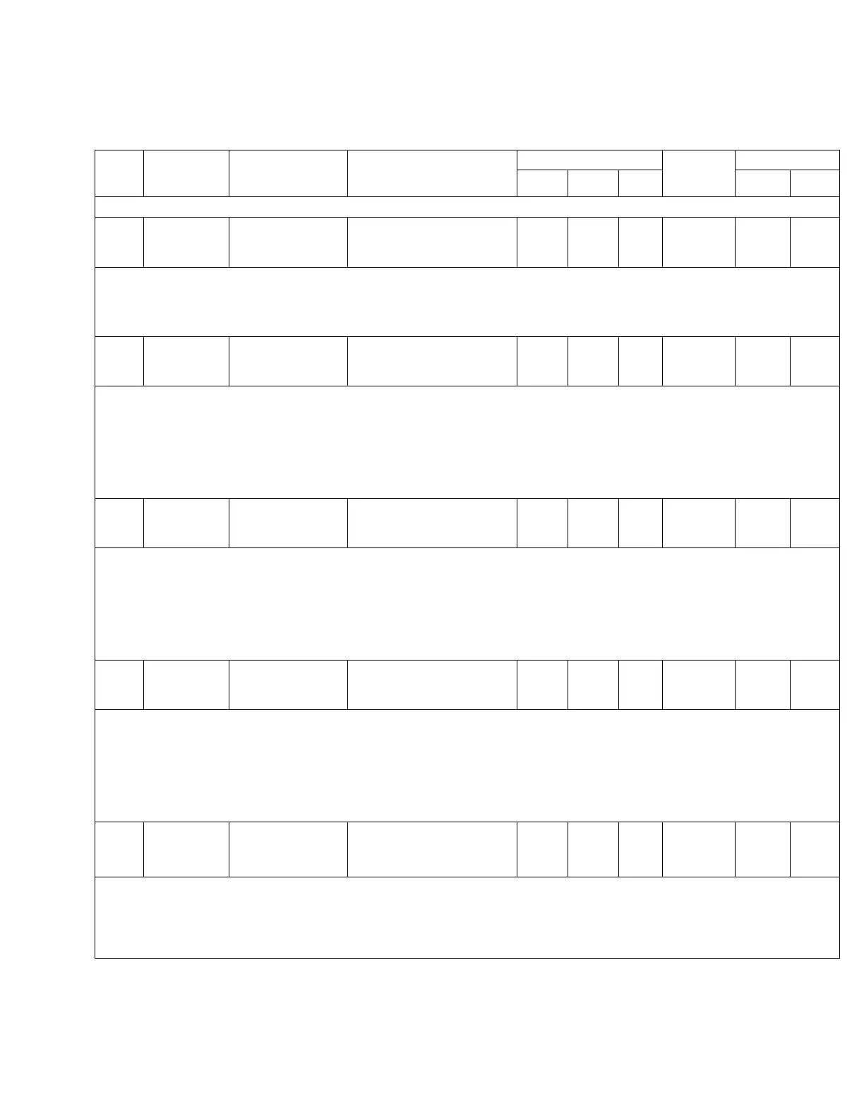
TABLE 5-3 Function Codes (continued)
Func.
Code
Level 1
Main Menu
Level 2
Sub-Menu
Level 3
Parameter
Security Level
Factory
Setting
Key Entry Limit
Read Edit Reset Low High
5 Settings Forward
Direction
005 Fwd Line Drop
Comp. Reactance
0.0 Volts
0 2 NA 0.0 -96.0 96.0
• The reactive line-drop compensation value is used to model the reactive line drop voltage between the regulator and the
center of regulation.
• The control uses this parameter, in conjunction with the regulator configuration (FC 41) and the load current, to calculate and
regulate to the compensated voltage (displayed at FC 8) during forward power flow.
6 Metering Instantaneous 006 Load Voltage
Secondary
XXX.X Volts
0 NA NA NA NA NA
• This is the fundamental RMS voltage, referred to the secondary, which appears at the output (load) terminals of the
regulator.
• Since ratio correction is performed by the firmware, this parameter is scaled according to the inputs at FC 43 (System Line
Voltage) and FC 44 (Overall PT Ratio).
• During reverse power operation, the control requires source voltage from a differential or source potential transformer or
from the source voltage calculation (see FC 39) to obtain this parameter. Lack of this voltage will result in the parameter
displaying dashes.
7 Metering Instantaneous 007 Source Voltage
Secondary
XXX.X Volts
0 NA NA NA NA NA
• This is the fundamental RMS voltage, referred to the secondary, which appears at the input (source) terminals of the
regulator.
• Since ratio correction is performed by the firmware, this parameter is scaled according to the inputs at FC 43 (System Line
Voltage) and FC 44 (Overall PT Ratio).
• During forward power operation, the control requires source voltage from a differential or source potential transformer or
from the source voltage calculation (see FC 39) to obtain this parameter. Lack of this voltage will result in the parameter
displaying dashes.
8 Metering Instantaneous 008 Compensated
Volt. Secondary
XXX.X Volts
0 NA NA NA NA NA
• This is the calculated voltage at the center of regulation, referred to the secondary.
• This is based on the resistive compensation setting (FC 4 or FC 54), reactive compensation setting (FC 5 or FC 55), and the
load current.
• This is the voltage that the regulator is regulating during either forward or reverse power flow.
• During reverse power operation, the control requires source voltage from a differential or source potential transformer or
from the source voltage calculation (see FC 39) to obtain this parameter. Lack of this voltage will result in the parameter
displaying dashes.
9 Metering Instantaneous 009 Load Current
Primary
XXX.X A
0 NA NA NA NA NA
• This is the fundamental RMS current flowing in the primary circuit.
• This parameter is scaled according to the CT primary rating which is entered at FC 45.
• During reverse power operation, the control requires source voltage from a differential or source potential transformer or
from the source voltage calculation (see FC 39) to obtain this parameter. Lack of this voltage will result in the parameter
displaying dashes.
37
CL-6 SERIES CONTROL INSTALLATION, OPERATION, AND MAINTENANCE INSTRUCTIONS MN225016EN January 2016
 Loading...


