TABLE 5-3 Function Codes (continued)
Func.
Code
Level 1
Main Menu
Level 2
Sub-Menu
Level 3
Parameter
Security Level Factory
Setting
Key Entry Limit
Read Edit Reset Low High
10 Metering Instantaneous 010 Load Voltage
Primary kV
XX.XX kV
0 NA NA NA NA NA
• This is the fundamental RMS voltage, referred to the primary, which appears at the output (load) terminals of the
regulator.
• During reverse power operation, the control requires source voltage from a differential or source potential transformer or
from the source voltage calculation (see FC 39) to obtain this parameter. Lack of this voltage will result in the parameter
displaying dashes.
11 Metering Instantaneous 011 Source Voltage
Primary kV
XX.XX kV
0 NA NA NA NA NA
• This is the fundamental RMS voltage, referred to the primary, which appears at the input (source) terminals of the
regulator.
• Since ratio correction is performed by the firmware, this parameter is scaled according to the inputs at FC 43 (System Line
Voltage) and FC 44 (Overall PT ratio).
• During forward power operation, the control requires source voltage from a differential or source potential transformer or
from the source voltage calculation (see FC 39) to obtain this parameter. Lack of this voltage will result in the parameter
displaying dashes.
12 Metering Instantaneous 012 Present Tap
Position
XX
0 3 NA NA -16 16
• This is the present position of the tap-changer.
• The tap position indication is synchronized at the neutral position, as indicated by the neutral light circuit. Tap positions are
displayed from -16 to 16, corresponding to 16 Lower (regulator bucking) to 16 Raise (regulator boosting), respectively.
• See the Control Features: Tap Position section of this manual.
• See Percent Regulation, FC 112.
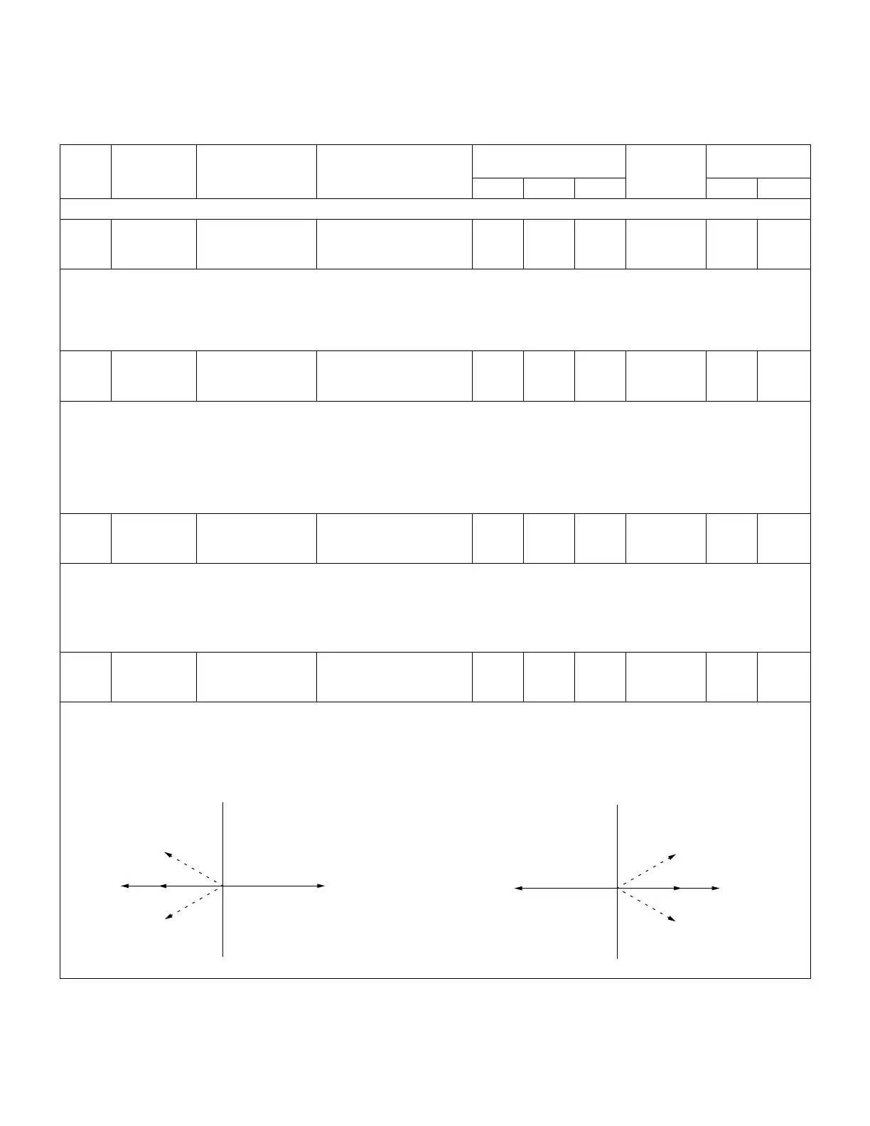
13 Metering Instantaneous 013 Power Factor
X.XXX
0 NA NA NA NA NA
• This is the power factor of the primary circuit, as represented by the phase difference between the line current and
voltage.
• Lagging current, or inductive loads, are designated by an implied (+) sign, and leading current, or capacitive loads, are
designated by a (-) sign. Refer to Figures 5-1 and 5-2.
Figure 5-1.
Reverse Power
Leading
(-)
Lagging
(+)
Unity
E
I
I
Reverse power vector diagram
Forward Power
Leading
(-)
Lagging
(+)
Unity
E
I
I
Figure 5-2. Forward power vector diagram.
38
CL-6 SERIES CONTROL INSTALLATION, OPERATION, AND MAINTENANCE INSTRUCTIONS MN225016EN January 2016
 Loading...


