Acoustic Performance Partnership Eastern Acoustic Works KF400a
One Main Street, Whitinsville MA, 01588 USA • Phone 508/234-6158 • Toll Free 800/992-5013 • Fax 508/234-8251 • Web http://www.eaw.com • email info@eaw.com
A
C
O
U
S
T
I
C
A
L
P
E
R
F
O
R
M
A
N
C
E
P
A
R
T
N
E
R
S
H
I
P
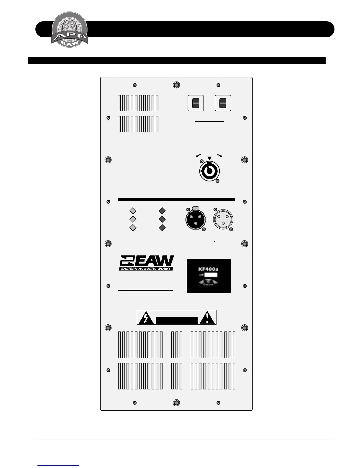
TECHNICAL SPECIFICATIONS KF400a
CLOSE COUPLED POWER™
MODULE
Fault LED
Indicates that protection
circuitry has shut down the
unit to avoid damage to
drivers or electronic devices.
Power ON LED
Indicates that the unit is
powered and ready for
operation.
HF/LF Output Current LEDs
Indicates output current for
both the high and low
amplifier channels.
HF/LF Limit LEDs
Indicates that protection
circuitry is actively limiting
output to protect the
drivers or electronic
components.
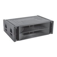
Rear Exhaust Grills
The fan exhaust grills are the
main exits for air drawn into
the unit for cooling. Avoid
blocking air flow.
Circuit Breakers
The AC Circuit Breakers
protect the unit from power
line faults and electronics
failure.
AC Input
Neutrik PowerCon locking AC
connector provides AC power
connection. Auto-sensing
power input operates from
95-125 VAC and 190-250
VAC.
Audio Signal Input
A balanced, 3-pin, female
XLR connector is provided for
the audio signal input
connection.
Audio Signal Loop Output
A balanced, 3-pin, male XLR
connector provides a
hardwired loop out of the
input signal.
CAUTION
RISK OF ELECTRIC SHOCK
DO NOT OPEN
MADE IN USA
PUSH
CLOSE COUPLED
POWER MODULE
Whitinsville, MA U.S.A.
AC INLET
LOOPINPUT
PIN 2=POS (+),
PIN 3=NEG (-)
PIN 1=GND ( )
CAUTION: TO PREVENT ELECTRIC SHOCK
DO NOT REMOVE COVERS. NO USER
SERVICEABLE PARTS INSIDE. RREFER TO
QUALIFIED SERVICE PERSONNEL.
DISCONNECT AC POWER BEFORE
ATTEMPTING SERVICE OR CONFIGURATION.
WARNINGS:
TO REDUCE THE RISK OF FIRE OR ELECTRIC
SHOCK DO NOT EXPOSE THIS EQUIPMENT
TO RAIN OR MOISTURE.
THIS SURFACE MAY BECOME HOT WHILE
THE UNIT IS OPERATING. ALLOW AT LEAST 6
INCHES CLEARANCE FROM THIS SURFACE
AND ADEQUATE VENTILATION TO ENSURE
RELIABLE OPERATION.
Power ON
HF Output Current
LF Output Current
Fault
HF Limit
LF Limit
I
O
7
A
M
P
S
I
O
7
A
M
P
S
PUSH
TO
RESET
CIRCUIT BREAKERS
UNLOCK LOCK
Operating voltage range:
Turn on 85VAC, turn off 260VAC
95-250VAC
50-60Hz
8A RMS
16A Peak
MAINS SUPPLY