EasyManua.ls Logo

ebm-papst M2E068-CF - User Manual

ebm-papst M2E068-CF
8 pages
Print Icon
To Next Page IconTo Next Page
Loading...
Operating instructions
M2E068-CF10-65
Translation of the original operating instructions
ebm-papst Mulfingen GmbH & Co. KG
Bachmühle 2
D-74673 Mulfingen
Phone +49 (0) 7938 81-0
Fax +49 (0) 7938 81-110
info1@de.ebmpapst.com
www.ebmpapst.com
CONTENTS
1. SAFETY REGULATIONS AND INFORMATION
11. SAFETY REGULATIONS AND INFORMATION
Read these operating instructions carefully before starting work on the
device. Observe the following warnings to prevent malfunctions or
danger to persons.
These operating instructions are to be regarded as part of the device.
The device is only to be sold or passed on together with the operating
instructions.
These operating instructions may be duplicated and distributed to inform
about potential dangers and their prevention.
1.1 Hazard levels for warnings
11.1 Hazard levels for warnings
These operating instructions use the following hazard levels to indicate
potentially hazardous situations and important safety regulations:
DANGER
Indicates an imminently hazardous situation which will result in
death or serious injury if the specified actions are not taken.
Compliance with the instructions is imperative.
WARNING
Indicates a potentially hazardous situation which can result in
death or serious injury if the specified actions are not taken.
Exercise extreme caution while working.
CAUTION
Indicates a potentially hazardous situation which can result in
minor or moderate injury or damage to property if the specified
actions are not taken.
NOTE
A potentially harmful situation can occur and, if not avoided, can
lead to property damage.
1.2 Staff qualifications
11.2 Staff qualifications
The device may only be transported, unpacked, installed, operated,
maintained and otherwise used by suitably qualified, trained and
authorized technical staff.
Only authorized specialists are permitted to install the device, to carry
out a test run and to perform work on the electrical installation.
1.3 Basic safety rules
11.3 Basic safety rules
The safety hazards associated with the device must be assessed again
following installation in the final product.
Note the following when working on the device:
; Do not perform any modifications, additions or conversions on the
device without the approval of ebm-papst.
1.4 Voltage
11.4 Voltage
; Check the device's electrical equipment at regular intervals; see
Chapter 5.2 Safety inspection.
; Replace loose connections and defective cables immediately.
DANGER
Electrically charged device
Risk of electric shock
When working on an electrically charged device, stand on a
rubber mat.
WARNING
Live terminals and connections even with device
switched off
Electric shock
21.5 Mechanical movement
21.6 Hot surface
21.7 Transport
21.8 Storage
22. INTENDED USE
33. TECHNICAL DATA
33.1 Product drawing
43.2 Nominal data
43.3 Technical description
43.4 Mounting data
43.5 Transport and storage conditions
44. CONNECTION AND STARTUP
44.1 Mechanical connection
54.2 Electrical connection
54.3 Connecting the cables
64.4 Connection diagram
74.5 Checking connections
74.6 Switching on the device
74.7 Switching off the device
75. MAINTENANCE, MALFUNCTIONS, POSSIBLE
CAUSES AND REMEDIES
75.1 Cleaning
75.2 Safety inspection
75.3 Disposal
Item no. 11403-5-9970 · ENU · Change 89188 · Approved 2016-04-18 · Page 1 / 8
Question and Answer IconNeed help?

Do you have a question about the ebm-papst M2E068-CF and is the answer not in the manual?

Summary

Safety Regulations and Information

Hazard Levels for Warnings

Defines DANGER, WARNING, CAUTION, NOTE hazard levels for safety instructions.

Staff Qualifications

Specifies requirements for personnel handling the device.

Basic Safety Rules

Outlines fundamental safety practices and notes for working on the device.

Voltage Safety Precautions

Warns about electrical hazards, including live terminals and the need for protective earth.

Mechanical Movement Hazards

Warns about entanglement hazards with rotating parts and ejected parts.

Hot Surface Warning

Alerts to high motor housing temperatures and risk of burns.

Transport Safety Guidelines

Provides safety instructions for transporting the motor, including PPE.

Storage Recommendations

Details recommended storage conditions for the device.

Intended Use and Improper Operation

Improper Use Prohibitions

Lists prohibited and hazardous operating conditions for the device.

Technical Data and Specifications

Product Drawing and Dimensions

Displays a detailed dimensional drawing of the motor with key measurements.

Nominal Data Summary

Presents essential technical specifications like voltage, current, power, and speed.

Technical Description Details

Details the motor's physical characteristics, insulation, and protection ratings.

Mounting Data Requirements

Provides information on screw clearance and suggests using self-locking screws.

Transport and Storage Conditions

Specifies maximum permitted ambient temperatures for transport and storage.

Connection and Startup Procedures

Mechanical Connection Guidelines

Covers mechanical installation aspects, including warnings about hot motor housing and handling.

Electrical Connection Safety

Details crucial electrical connection steps, emphasizing protective earth and voltage.

Pre-Connection Requirements

Lists checks before connecting, including nameplate data and power supply matching.

Voltage Control Considerations

Warns about potential issues like excessive current and noise with voltage control.

Variable Frequency Drive (VFD) Use

Advises on VFD use, recommending filters and checking motor heating.

Cable Connection Instructions

Explains how to connect external leads, starting with the protective earth.

Connection Diagram Guide

Provides a visual guide for wiring the device, including wire color codes.

Post-Connection Checks

Lists checks to ensure proper installation, including isolation and cable fit.

Device Switching On Procedure

Outlines prerequisites and steps for safely switching on the installed device.

Device Switching Off Procedure

Describes the procedure for safely disconnecting power from the device.

Maintenance, Malfunctions, and Remedies

Cleaning Guidelines

Provides guidelines for cleaning the device safely, avoiding water jets and harsh chemicals.

Safety Inspection Schedule

Details periodic checks for damage, cable fastening, and drainage holes.

Disposal Recommendations

Discusses environmental commitment and recommendations for product disposal.

Country-Specific Disposal Requirements

Emphasizes adherence to local regulations for product disposal.

Disassembly Safety and Procedure

Provides safety warnings and procedures for disassembling the product by qualified personnel.

Component Recycling Guidance

Guides on separating and recycling various material components of the device.

Overview

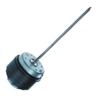
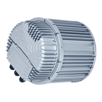
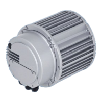
This document describes the M2E068-CF10-65, an external rotor motor manufactured by ebm-papst Mulfingen GmbH & Co. KG, designed exclusively for use as a drive motor.

Function Description

The M2E068-CF10-65 is a single-phase drive motor. It is designed to operate within a specified ambient temperature range and with all protective devices in place, following the provided operating instructions. The motor's rotating parts are designed for a maximum of one million load cycles.

Important Technical Specifications

General Data:

  • Motor Type: M2E068-CF
  • Phase: 1~
  • Nominal Voltage: 230 VAC
  • Frequency: 50 Hz
  • Method of obtaining data: me (Max. efficiency)
  • Valid for approval/standard: CE
  • Speed: 2600 rpm
  • Power Consumption: 85 W
  • Power Output: 47 W
  • Current Draw: 0.38 A
  • Rated Torque: 17.4 Ncm
  • Mean Starting Torque: 11.5 Ncm
  • Capacitor: 2 µF
  • Capacitor Voltage: 450 VDB
  • Min. Ambient Temperature (Operating): -25 °C
  • Max. Ambient Temperature (Operating): 45 °C
  • Starting Current: 0.74 A

Mechanical and Environmental Data:

  • Fan Size: 68 mm
  • Rotor Surface: Painted black
  • Direction of Rotation: Clockwise, viewed toward rotor
  • Degree of Protection: IP44 (installation- and position-dependent as per EN 60034-5)
  • Insulation Class: "B"
  • Moisture (F) / Environmental (H) Protection Class: H0+
  • Installation Position: Shaft horizontal or rotor on top; rotor on bottom on request
  • Condensation Drainage Holes: On stator side
  • Mode: S1
  • Motor Bearing: Ball bearing
  • Touch Current (according to IEC 60990): < 0.75 mA
  • Motor Protection: Thermal overload protector (TOP) internally connected
  • Protection Class (with customer connection of protective earth): I
  • Conformity with Standards: EN 60335-1; CE
  • Max. Permitted Ambient Temp. for Motor (Transport/Storage): +80 °C
  • Min. Permitted Ambient Temp. for Motor (Transport/Storage): -40 °C
  • Strength Class of Screws: 8.8

Dimensions (refer to product drawing):

  • Overall length: 182 mm
  • Motor body diameter: Ø80 mm
  • Shaft diameter: Ø8 mm
  • Mounting hole pattern: 4x 90° with M4 screws, depth max. 5mm
  • Cable: PVC 4G 0.5 mm², 4x crimped splices

Usage Features

Installation:

  • The device must be transported, unpacked, installed, operated, maintained, and otherwise used by suitably qualified, trained, and authorized technical staff.
  • Only authorized specialists are permitted to install the device, carry out a test run, and perform work on the electrical installation.
  • Secure the device against unintentional loosening, e.g., using self-locking screws.
  • Ensure the device is securely positioned until all fastening screws are tightened to prevent damage from slipping.
  • The device has external leads. The "PE" (protective earth) must be connected first.
  • Cables should be connected according to the application, observing the connection diagram.
  • Ensure isolation from the supply (all phases) before checking connections.
  • The device may only be switched on if it has been installed properly and in accordance with its intended use, including required safety mechanisms and professional electrical hookup.
  • Before switching on, check for visible external damage and ensure protective devices are functional.
  • Check the fan's airflow paths for foreign matter and remove any found.
  • Apply the nominal supply voltage.
  • To switch off, disconnect the device from the power supply at the supply line's main switch, disconnecting the ground connection last.

Electrical Connection:

  • Always connect a protective earth first and check its integrity.
  • Use only cables that meet specified installation regulations for voltage, current, insulation material, and capacity.
  • Route cables to prevent contact with any rotating parts.
  • Prevent water ingress into wires or cables at the customer end to avoid device damage.
  • Connect the device only to circuits that can be switched off with an all-pole disconnection switch.
  • Verify nameplate data matches connection data and operating capacitor data.
  • Ensure power supply matches device voltage.
  • Use cables designed for the current level indicated on the nameplate, with cross-section determined according to EN 61800-5-1. The protective earth must have a cross-section equal to or greater than the phase conductor.
  • Recommended use of 105 °C cables, with a minimum cross-section of AWG 26 / 0.13 mm².
  • Ground conductor contact resistance according to EN 60335 must be verified in the end application. An additional protective earth conductor may be necessary depending on installation circumstances.

Voltage Control:

  • With speed control using transformers or electronic voltage regulators (e.g., phase control), excessive current may occur. Noises may also occur with phase control depending on installation.
  • For operation with variable frequency drives, install sinusoidal filters on all poles (phase-phase and phase-ground) between the drive and the motor. This protects against high-voltage transients and harmful bearing currents.
  • Heating of the motor due to variable frequency drive use must be checked by the customer in the application.

Safety Warnings:

  • DANGER (Electrically charged device): Risk of electric shock. Stand on a rubber mat when working on an electrically charged device.
  • WARNING (Live terminals): Risk of electric shock even when switched off. Wait five minutes after disconnecting voltage before opening.
  • CAUTION (Rotor and impeller energized): In case of a fault, do not touch the rotor and impeller once installed.
  • CAUTION (Automatic restart): The motor restarts automatically when operating voltage is applied. Keep out of the danger zone. Switch off line voltage and ensure it cannot be switched back on. Wait for the motor to stop.
  • WARNING (Rotating device): Long hair, loose clothing, and jewelry can become entangled. Wear a cap and avoid loose items.
  • WARNING (Ejected parts): Missing protective devices can allow balancing weights or broken fan blades to be ejected. Install guard grilles and keep out of the exhaust zone.
  • CAUTION (Hot surface): High temperature on motor housing. Ensure sufficient protection against accidental contact.
  • CAUTION (Transport): Crushing hazard. Wear safety shoes and cut-resistant gloves. Transport in original packaging only. Secure the device to prevent slipping.
  • WARNING (Hot motor housing): Risk of fire. Ensure no combustible or flammable materials are near the motor.
  • CAUTION (Cutting and crushing hazard): Carefully remove from packaging, avoid shocks. Wear safety shoes and cut-resistant gloves.
  • CAUTION (Possible damage): If the device slips during installation, serious damage can result. Secure the device until all fastening screws are tightened.

Maintenance Features

Storage:

  • Store the device, partially or fully assembled, in a dry, weatherproof, and clean environment in its original packaging.
  • Protect against environmental effects and dirt until final installation.
  • Recommended storage is no longer than one year to guarantee trouble-free operation and longest possible service life.
  • Maintain storage temperature as specified in Chapter 3.5.

Cleaning:

  • Do not clean the device using a water jet or high-pressure cleaner.
  • Do not use acid, alkali, or solvent-based cleaning agents.
  • Do not use pointed or sharp-edged objects for cleaning.

Safety Inspection (at least every 6 months):

  • Device for damage: Visual inspection. Replace device if damaged.
  • Fastening the cables: Visual inspection. Fasten if loose.
  • Fastening the protective earth terminal: Visual inspection. Fasten if loose.
  • Insulation of cables for damage: Visual inspection. Replace cables if damaged.
  • Condensation drainage holes for clogging: Visual inspection. Open holes if clogged.

Malfunctions and Remedies:

  • Rotor not running smoothly:
    • Possible cause: Imbalance in rotating parts.
    • Possible remedy: Clean the device; replace if imbalance persists after cleaning.
  • Motor not turning:
    • Possible cause: Mechanical blockage.
    • Possible remedy: Switch off, isolate from supply, and remove mechanical blockage.
  • Line voltage faulty:
    • Possible cause: Faulty connection.
    • Possible remedy: Check line voltage, restore power supply. Isolate from supply, correct connection; see connection diagram.
  • Motor overtemperature:
    • Possible cause: Thermal overload protector activated.
    • Possible remedy: Allow motor to cool off, locate and rectify cause of error, release restart lockout if necessary.
    • Possible cause: Impermissible point of operation.
    • Possible remedy: Check point of operation.
    • Possible cause: Ambient temperature too high.
    • Possible remedy: Reduce ambient temperature if possible.
    • Possible cause: Deficient cooling.
    • Possible remedy: Improve cooling.
  • In the event of further malfunctions, contact ebm-papst.

Disposal:

  • Disassembly must be performed or supervised by qualified personnel.
  • The product is to be disassembled into suitable components for disposal using standard procedures for motors.
  • WARNING (Heavy parts): Some components are heavy and could drop off during disassembly, causing injury or damage. Secure components before unfastening.
  • Component Disposal: Products are mostly made of steel, copper, aluminum, and plastic. Metallic materials are generally recyclable. Separate components into categories: steel and iron, aluminum, non-ferrous metal (motor windings), plastics (particularly with brominated flame retardants), insulating materials, cables and wires, electronic scrap (circuit boards).
  • Ferrite magnets (used in external rotor motors) can be disposed of like normal iron and steel.
  • Electrical insulating materials (on the product, in cables and wires) are similar and should be treated the same way. These include miscellaneous insulators in the terminal box, power cables, internal wiring cables, and electrolytic capacitors.
  • Dispose of electronic components using proper procedures for electronic scrap.
  • Contact ebm-papst for any other disposal questions.
  • Always observe applicable country-specific legal regulations for product or waste disposal.

ebm-papst M2E068-CF Specifications

General IconGeneral
Brandebm-papst
ModelM2E068-CF
CategoryEngine
LanguageEnglish

Related product manuals