Operating instructions
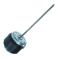
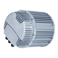
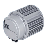
M2E068-CF10-65
Translation of the original operating instructions
3.2 Nominal data
Motor M2E068-CF
Phase 1~
Nominal voltage / VAC 230
Frequency / Hz 50
Method of obtaining
data
me
Valid for approval/
standard
CE
Speed (rpm) / min
-1
2600
Power consumption / W 85
Power output / W 47
Current draw / A 0.38
Rated torque / Ncm 17.4
Mean starting torque
/ Ncm
11.5
Capacitor / µF 2
Capacitor voltage / VDB 450
Min. ambient
temperature / °C
-25
Max. ambient
temperature / °C
45
Starting current / A 0.74
ml = Max. load · me = Max. efficiency · fa = Free air
cs = Customer specification · ce = Customer equipment
Subject to change
3.3 Technical description
Fan size 68 mm
Rotor surface Painted black
Direction of rotation Clockwise, viewed toward rotor
Degree of protection IP44; installation- and position-dependent
as per EN 60034-5
Insulation class "B"
Moisture (F) /
Environmental (H)
protection class
H0+
Installation position Shaft horizontal or rotor on top; rotor on
bottom on request
Condensation
drainage holes
On stator side
Mode S1
Motor bearing Ball bearing
Touch current
according to IEC
60990 (measuring
circuit Fig. 4, TN
system)
< 0.75 mA
Motor protection Thermal overload protector (TOP)
internally connected
with cable Variable
Protection class I (with customer connection of protective
earth)
Conformity with
standards
EN 60335-1; CE
With regard to cyclic speed loads, note that the rotating parts of
the device are designed for a maximum of one million load
cycles. If you have special questions, consult ebm-papst for
support.
3.4 Mounting data
For screw clearance, see Chapter 3.1 Product drawing
; Secure the screws against unintentional loosening (e.g. use self-
locking screws).
Strength class of
screws
8.8
Any further mounting data required can be taken from the product drawing.
3.5 Transport and storage conditions
; Use the device in accordance with its degree of protection.
Max. permitted
ambient temp. for
motor (transport/
storage)
+ 80 °C
Min. permitted
ambient temp. for
motor (transport/
storage)
- 40 °C
4. CONNECTION AND STARTUP
4.1 Mechanical connection
WARNING
Hot motor housing
Risk of fire
→ Ensure that no combustible or flammable materials are
located close to the motor.
CAUTION
Cutting and crushing hazard when removing motor from
packaging
→ Carefully remove the device from its packaging. Strictly
avoid shocks.
→ Wear safety shoes and cut-resistant safety gloves.
; Check the device for transport damage. Damaged devices are not to
be installed.
; Install the undamaged device in accordance with your application.
CAUTION
Possible damage to the device
If the device slips during installation, serious damage can result.
→ Ensure that the device is securely positioned at its place of
installation until all fastening screws have been tightened.
Item no. 11403-5-9970 · ENU · Change 89188 · Approved 2016-04-18 · Page 4 / 8