Do you have a question about the Ebyte E32-900T20D and is the answer not in the manual?
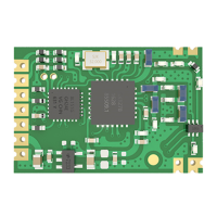
Introduces the E32-900T20D module based on SX1276 RF chip.
Lists various applications for the wireless module.
Defines the operational limits for voltage, power, and temperature.
Details operational parameters like voltage, temperature, frequency, and power consumption.
Explains the fixed point-to-point data transmission method.
Describes how data is sent to multiple receivers simultaneously.
Details setting addresses for broadcast communication.
Explains how to set up address for monitoring communication.
Describes the module reset process and AUX behavior.
Explains the function and usage of the AUX pin.
Details AUX pin indication for UART output timing.
Explains AUX pin indication for wireless transmitting buffer status.
Describes the module's self-check and configuration process.
Provides important notes and considerations for using the AUX pin.
Explains how to switch between the module's operating modes using M0 and M1.
Details the Normal mode (M1=0, M0=0) for transparent transmission.
Describes the Wake-up mode (M1=0, M0=1) for low-power communication.
Explains the Power-saving mode (M1=1, M0=0) for monitoring.
Details the Sleep mode (M1=1, M0=1) for parameter setting.
Lists the default configuration values for the module.
Describes the command to read current module parameters.
Explains the command to retrieve the module's version information.
Details the command to reset the module to default settings.
Covers commands for setting module parameters.
Provides recommendations for hardware design and power supply.
Discusses factors affecting short communication range.
Explains common causes of module damage and prevention.
Addresses high Bit Error Rate issues and solutions.
Details temperature profiles for reflow soldering.
Illustrates the temperature curve for reflow soldering.
| Transmission Power | 20 dBm |
|---|---|
| Interface | UART |
| Baud Rate | 1200-115200bps |
| Distance | 3000m |
| Operating Temperature | -40 to +85 °C |
| Air Data Rate | 0.3-19.2kbps |
| Encryption | AES-128 |