Do you have a question about the Ebyte E01-ML01DP5 and is the answer not in the manual?
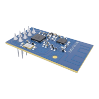
The E01-ML01DP5 is a DIP module based on the original imported nRF24L01P from Nordic, Norway. It operates at 2.4GHz with a transmitting power of 100mW. This module is designed for various applications requiring reliable wireless communication.
The E01-ML01DP5 module integrates a power amplifier (PA) and a low noise amplifier (LNA), which significantly enhance its maximum transmit power to 100mW and improve receiving sensitivity. This design addresses the limitations often encountered in modules without dedicated PA and LNA components, leading to a much-improved performance in terms of range and signal integrity.
The module supports an air data rate of 2Mbps, 1Mbps, and 250kbps, providing flexibility for different communication needs. It offers 125 communication channels, which are crucial for multi-point communication, grouping, and frequency hopping applications, allowing for robust and interference-resistant wireless links.
Communication with a microcontroller (MCU) is facilitated through an SPI interface, supporting data rates from 0 to 10 Mbps. This high-speed interface ensures efficient data exchange between the module and the host system. The module also features Enhanced ShockBurst, which is fully compatible with all NORDIC nRF24L, nRF24E, and nRF24U series devices, simplifying integration into existing nRF-based systems.
The IRQ pin can be utilized as an interrupt pin to wake up the MCU and achieve a fast response, which is beneficial for power-saving and real-time applications. Alternatively, the interrupt status can be obtained via SPI, though this method is generally not recommended due to its impact on overall power consumption and efficiency.
The CE pin can be kept at a high level for extended periods. However, it is essential to set the module to POWER DOWN mode when writing to its registers. It is recommended that the CE pin be controlled by an MCU pin for optimal management. The CE pin is connected to the LNA enable pin; when CE is high (1), the LNA is turned on, and when CE is low (0), the LNA is turned off. This operation is perfectly synchronized with the transceiver mode of the nRF24L01, meaning users do not need to manage the LNA operation separately.
For automatic response functionality, the CE pin must remain at a high level during transmission, rather than being held high for only 10µs as specified in some datasheets. The recommended operation is to set CE to high (1) when the module begins sending. After all data has been sent, CE should be set to low (0). This approach is crucial because the module immediately transitions into receiving mode after sending. If CE is low (0) at this point, the LNA will be closed, which negatively impacts receiving sensitivity.
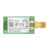
The E01-ML01DP5 is designed for ease of use with its DIP package and SMA interface. The SMA interface allows for easy connection of coaxial cables or external antennas, providing flexibility in antenna placement and type. This is particularly useful for optimizing communication distance and signal quality.
The module supports a wide power supply range of 2.0V to 3.6V. For best performance, a power supply over 3.3V is recommended. The communication level is 3.3V, and users should be cautious when interfacing with 5V TTL systems, as this may pose a risk of damage to the module. If a 5V level communication line is necessary, a 1k-5.1k resistor must be connected in series, though this is not the recommended approach due to residual risk.
The module operates reliably across an industrial temperature range of -40°C to 85°C, making it suitable for demanding environments and long-term operation. Its robust design and component selection adhere to industrial-grade standards, ensuring high precision and stability.
The E01-ML01DP5 has obtained FCC, CE, and RoHS certifications, indicating compliance with international regulatory standards for electromagnetic compatibility and environmental safety.
This module is versatile and can be applied in various fields, including wearable devices, smart home and industrial sensors, security and positioning systems, wireless remote control (including drones and game controllers), healthcare products, wireless voice communication, wireless headsets, and automotive industry applications. Its robust performance and flexible features make it an ideal choice for a wide array of wireless communication projects.
To ensure the longevity and stable operation of the E01-ML01DP5 module, several hardware design considerations and maintenance practices are recommended:
| Frequency | 433 MHz |
|---|---|
| Modulation | FSK |
| Transmission Power | 20 dBm |
| Interface | UART |
| Operating Temperature | -40°C to +85°C |
| Operating Voltage | 1.9V ~ 3.6V |