Do you have a question about the ECA GSM-18V3 and is the answer not in the manual?
Ensure the unit is disconnected from power before inserting or removing the SIM card.
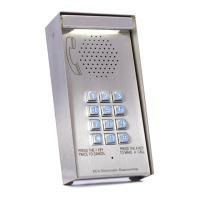
Connect Antenna, Speaker, Mic, Push Button, and Intercom Panel as per diagram.
Apply silicon on terminals 3 & 4 to prevent short circuits after installation.
Install the GSM antenna high and do not fold excess wire.
Operates on 12V-24V AC/DC. Yellow wire is Negative, Orange is Positive for DC.
Wait 25 seconds after power connection for unit setup and LED flashing.
Unit stores up to 1000 phone numbers for authorized access.
Grey (COM) and Purple (N.O.) wires activate gate, garage door, or alarm.
Select Pulse (Dip-Switch #3 OFF) or Latch (Dip-Switch #3 ON) for relay activation.
Add/delete user numbers, lock/unlock system via MASTER number.
Set Dip-Switch #1 ON, then dial unit's number to enter Program Mode.
Press *+4+*+# to delete all phone numbers except the MASTER number.
Press 000 + * + phone number + # to program the Master Phone Number.
Press 001 + * + phone number + # to program the first User Phone Number.
Press * + 0 + # to exit Program Mode and hang up.
Press * + 4 + 'phone number' + # to delete a specific known number.
Press * + 4 + * + * + * + # to delete all numbers except MASTER.
Press * + 2 + # to lock the system.
Press * + 3 + # to unlock the system.
Answers only MASTER number; operates relay for authorized users.
Automatically registers incoming numbers and activates relay.
Negative TRIGGER input activates intercom; user can activate relay via '#' key.
Check gate status (open/closed) via STATUS input connected to magnet switch.
Press * + 6 + # to check if STATUS input is CLOSE LOOP or OPEN LOOP.
| Brand | ECA |
|---|---|
| Model | GSM-18V3 |
| Category | Intercom System |
| Language | English |