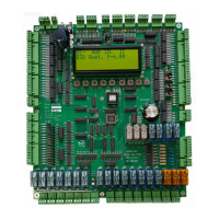
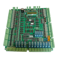
The ECD 100-194 EN81 Controller is a sophisticated electronic circuit designed for lift control systems, adhering to the Lift Standard EN81-20/50. This manual, updated on January 23, 2023, provides comprehensive operational guidelines, technical specifications, and maintenance procedures for the device.
Function Description
The ECD 100-194 is a 12-stop, simplex or duplex (up to 6 car group), fully collective controller. Its primary function is to manage the movement and operation of lifts, ensuring compliance with safety regulations and efficient performance. The controller integrates various inputs and outputs to manage door operations, car calls, hall calls, and safety features. It supports different drive types, including hydraulic and various VF drives, and incorporates advanced counting methods for precise floor positioning.
Important Technical Specifications
Safety Regulations & Introduction:
The controller is designed to meet AS1735 for Australia and all applicable local codes. It requires safe handling and proper operation, with a strong emphasis on operator obligations and hazard awareness. High voltages (0V and +24V lines) are critical, and proper wiring is essential to prevent damage. The controller cabinet must be installed in a location free from dust, dirt, excessive heat and humidity, mist, or water. It is designed to operate within a temperature range of 40°C / 104°F.
EEPROM (Lift Parameter) Settings:
The controller's parameters are stored in EEPROM and can be adjusted via an LCD display. Key parameters include:
- BOT (Bottom floor number): Setting example: BOT 01: 00000001 (Level 1).
- TOP (Top floor number): Setting example: TOP 08: 00001000 (Level 8).
- BCC (Bottom floor car call for "BOT CALL" button on the circuit board): Setting example: BCC 00: 10000000 (Level 1).
- TCC (Top floor car call for "TOP CALL" button on the circuit board): Setting example: TCC 01: 00000001 (Level 8).
- TCI (Top floor car call extension): Setting example: TCI 00: 00000000.
- CCM (Car call mask): Setting example: CCM FF: 11111111 (Levels 1-8).
- UCI (Up call mask): Setting example: UCM FF: 11111111 (Levels 1U-8U).
- DCM (Down call mask): Setting example: DCM FF: 11111111 (Levels 2D-8D).
- DCI (Down call extension): Setting example: DCI 00: 00000000.
- LOB (Lobby floor): Setting example: LOB 40: 01000000 (Level 2 master floor).
- ZON (Zone floor): Setting example: ZON 10: 00010000 (Zone to Level 4).
- ZTM (Zoning time): Setting example: ZTM 06: 00000110 (= 60seconds).
- HFS (Hall fire service floor): Setting example: HFS 80: 10000000 (Level 1).
- SFR (Short Floor Run): Setting example: SFR 9F: 10011111 (Short floor between 2&3).
- L# (Lift Number): Setting example: L# 02: 00000010 (Lift #2).
- MOD (Mode inputs): Setting example: #L 03: 00000011 (3 Lifts in group).
- CNT (Intermediate floor car call for "INTER" button on the circuit board): Setting example: CNT 02: 00000010 (DOB input inverted).
- CIM (Intermediate floor car call for "INTER" button on the circuit board): Setting example: CIM 23: 00100011 (Set to Levels 3, 7 and 8).
- LOK (Single or Dual Lock circuit): Setting example: LOK 01: 00000001 (Single door locks).
- RPT (Run protection timer): Setting example: RPT 14: 00010100 (20s). Min 14, Max 2D.
- DRV (Drive control type): Setting example: DRV 02: 00000010 (3010/2CH/S block).
- ST2 (Star Delta time): Setting example: ST2 08: 00001000 (= 800ms).
- SDX (Star Delta Exchange time): Setting example: SDX 01: 00000001 (= 100ms).
- MSL (Magnet slowing type): Setting example: MSL 00: 00000000 (MSU/MSD slowing).
- RTM (Run Time Short floor run timer): Setting example: RTM A5: 10100101.
- XTM (Extend run time): Setting example: XTM 1F: 11111111 (Extended fast speed run time by 20).
- StF (Start Fast): Setting example: StF 20: 00100000 (Number of pulses it takes to reach fast speed).
- StM (Start Medium): Setting example: StM 1F: 11111111 (Number of pulses it takes to reach medium speed).
- SlF (Slow Fast): Setting example: SlF 1F: 11111111 (Number of pulses it takes to slow from fast speed).
- SlM (Slow Medium): Setting example: SlM 1F: 11111111 (Number of pulses it takes to slow from medium speed).
- BST (Brake Switch Time): Setting example: BST 13: 00010011 (2s).
- DPT (Door Protection Time): Setting example: DPT FF: 11111111 (25s).
- UIM (Unintended Movement testing): Setting example: UIM 01: 00000001 (UIM Test enabled).
- BSW (Brake Switch Polarity): Setting example: BSW 01: 00000001 (normally open brake contact).
- DLM (Door limit mask): Setting example: DLM 00: 00000000 (Single doors).
- DLI (Door limit invert): Setting example: DLI 00: 00000000 (Limits not inverted).
- NDG (Nudging Relay for door nudging/Passing tone): Setting example: NR 00: 00000000 (Nudging off).
- ADO (Advanced Door Opening): Setting example: ADO 00: 00000000 (off).
- DTC (Door time car call): Setting example: DTC 32: 00110010 (5000ms, "5 seconds").
- DTH (Door time hall call): Setting example: DTH 32: 00110010 (5000ms, "5 seconds").
- DTL (Door time lobby call): Setting example: DTL 32: 00110010 (5000ms, "5 seconds").
- ANS (Anti Nuisance EDP): Setting example: ANS 00: 00000000.
- SSD (Soft Start Drive): Setting example: SSD 01: 00000001 (Hydraulic lift with Soft Starter motor starting).
- FD1 (Front Doors 1-8 mask): Setting example: FD1 F0: 11110000 (Front doors 1-4).
- RD1 (Rear doors 1-8 mask): Setting example: RD1 08: 00001000 (Rear doors 5).
- SD1 (Selective rear doors 1-8 mask): Setting example: SD1 10: 00010000 (Levels 4 & 5 selective).
- DTR (Once the lift arrives at the HR floor, the doors shall remain open for the time set as per DTR): Setting example: DTR 32: 00110010 (5000ms, "5 seconds").
- HRF (Hospital/Hall Recall Floor): Setting example: HRF 40: 01000000 (Set to Level 2).
- HR1 (Hospital/Hall Recall 1 setup): Setting example: HR1 40: 01000000 (Level 10).
- PRK (Park/Zone with doors closed/open): Setting example: PRK 10: 00010000 (Set to Level 10).
- ALP (Auxiliary Leveling Pump): Setting example: ALP FF: 11111111 (No Auxiliary pump Re-level).
- PI (Position Indication): Setting example: PI 00: 00000000 (Decimal outputs).
- DT (Door Time Close Setup): Setting example: DT 01: 00000001 (DTC/DTH cancelling activated).
- LCK (EEPROM Lock): Setting example: LCK 00 (unlock default 67).
- COD (Code Lock): Setting example: COD 00 (unlock default 89).
Group Connections and Communication:
The controller supports group operations, with 24Vdc and 0Vdc, up and down hall calls, and HFS inputs looped between all elevators in the group. RS485 3-wire system is used for serial communication. Controllers are linked at the Serial TX terminals, SX+, SX- and GND, using shielded 3-wire serial cable. A "Terminator" jumper link is installed above the LCD on the last lift of the group. The same version software (build date) must be used in all grouped controllers.
Inputs – Outputs:
The controller features high voltage AC inputs (SAF, CG, LCK1, LCK2, M1 and M3) and low voltage DC inputs (1P to 12P, 24Vdc). It includes transistor outputs (1P-12P, DDN, DUP, OS, HBS) and Darlington outputs. Specific inputs and outputs include:
- BKS1 – BraKe Switch 1 input: Monitors brake status.
- BKS2 – BraKe Switch 2 input: Monitors secondary brake status.
- BRK – BraKe relay output: Controls brake operation.
- BSL – Bottom Slowing Limit input: Manages bottom slowing and activates BSL-limit switch.
- BSW – Bypass onboard switch: Rotary selector switch for bypass operations.
- BPAV – Bypass Switch Audio Visual alert output: Provides audio-visual alerts during bypass.
- CFS – Car Fire Service input: Initiates car fire service mode.
- CFSS – Car Fire Service Start input: Starts car fire service.
- CG – Car Gate AC input: Monitors car gate status.
- CG relay – Car Gate relay: Controls car gate.
- CGM LED – Car Gate Monitoring LED: Indicates car gate monitoring status.
- CLP – Car Light and Power output: Controls car light and power.
- COR – COrrection Run output: Manages correction run.
- DC – Door Close relay output: Controls door closing.
- DCB – Door Close Button input: Monitors door close button.
- DDN – Door Down output: Transistor output for door down.
- DF – Down Fast relay output: Controls fast down movement.
- DFC – Door Fully Closed input: Monitors door fully closed status.
- DFO – Door Fully Open input: Monitors door fully open status.
- DN – Door Down relay output: Controls door down movement.
- DO – Door Open relay output: Controls door opening.
- DOB – Door Open Button input: Monitors door open button.
- DDO – Door Disable onboard toggle switch: Disables door operation.
- DS – Down Slow relay output: Controls slow down movement.
- DUP – Direction UP output: Transistor output for direction up.
- DZ – Door Zone input: Monitors door zone.
- DZR – Door Zone Rear output: Controls rear door zone.
- DZ relay: Controls door zone.
- EDP – Electronic Door Protection input: Monitors electronic door protection.
- EP – Emergency Power input: Monitors emergency power.
- EQK – EarthQuake detection input: Detects earthquake.
- HBS – Hall Button Stop output: Stops hall buttons.
- HCB – Hall Call Bypass input: Bypasses hall calls.
- HFS – Hall Fire Service input: Monitors hall fire service.
- HRI – Hospital / Hall Recall input: Initiates hospital/hall recall.
- HRO – Hall (Hospital) Recall Output: Provides hall recall output.
- IDN – Inspection Down input: Monitors inspection down.
- IND – INdependent service input: Initiates independent service.
- INSP – INSPection control input: Monitors inspection control.
- INSP COM onboard push button: Controls inspection.
- INSP DN onboard push button: Controls inspection down.
- INSP UP onboard push button: Controls inspection up.
- IRO – Inspection Relay Output: Provides inspection relay output.
- IUP – Inspection UP input: Monitors inspection up.
- LCK1 – LocK 1 input: Monitors lock 1.
- LCK1M LED – LCK1 Monitoring LED: Indicates lock 1 monitoring.
- LCK2 – LocK 2 input: Monitors lock 2.
- LEV relay: Controls leveling.
- LOCK VALVE SWITCH onboard toggle switch: Controls lock valve.
- L1BP relay: Controls bypass 1.
- L2BP relay: Controls bypass 2.
- MSD – Magnetic Switch Down input: Monitors magnetic switch down.
- MSU – Magnetic Switch Up input: Monitors magnetic switch up.
- M1 – M1 output terminal: Output terminal M1.
- M3 – M3 input: Input M3.
- M4 – M4 terminal: Output terminal M4.
- N – Neutral terminal: Neutral terminal.
- NDG – NuDGing buzzer output: Provides nudging buzzer output.
- NR – NuDging Relay output: Controls nudging relay.
- OIL – OIL overheat input: Monitors oil overheat.
- OS – Out of Service output: Indicates out of service.
- OVL – OverLoad input: Monitors overload.
- OVLO – OverLOad output: Provides overload output.
- PAWL – PAWL device output: Controls PAWL device.
- PCOM – Pit COMmon input: Monitors pit common.
- PINS – Pit INSPection input: Monitors pit inspection.
- PRES – Pit INSPection RESet input: Resets pit inspection.
- PRK – PaRKIng input: Monitors parking.
- PRV – PRoVing circuit input: Monitors proving circuit.
- PULSE – PULSE counting input: Monitors pulse counting.
- PWLE – PaWL device Extended input: Monitors extended PAWL device.
- PWLR – PaWL device Retracted input: Monitors retracted PAWL device.
- SAF – SAFety circuit input: Monitors safety circuit.
- Sln1 – Input: Input Sln1.
- Sln2 – Input: Input Sln2.
- Sln3 – Input: Input Sln3.
- SO1 – Output: Output SO1.
- SO2 – Output: Output SO2.
- SO3 – Output: Output SO3.
- SO4 – Output: Output SO4.
- SP1 – SPare relay output 1: Spare relay output 1.
- SP2 – SPare relay output 2: Spare relay output 2.
- SP3 – SPare relay output 3: Spare relay output 3.
- SP4 – SPare relay output 4: Spare relay output 4.
- SX – Serial communication input: Monitors serial communication.
- SX+ – Serial communication input: Monitors serial communication.
- TCOM – Top of car INSPection COMmon input: Monitors top of car inspection common.
- TSL – Top Slowing Limit input: Monitors top slowing limit.
- UD – Up Dn relay output: Controls up/down relay.
- UF – Up Fast relay output: Controls fast up movement.
- UIM – UnIntended Movement output: Indicates unintended movement.
- UP – UP relay output: Controls up relay.
- US – Up Slow relay output: Controls slow up movement.
- 1C/12C – Car Call input / output: Monitors car call.
- 2D/12D – Down Hall Call input / output: Monitors down hall call.
- 1P/12P – Position output: Provides position output.
- 1U/11U – Up Hall Call input / output: Monitors up hall call.
LCD Display:
The controller features a Liquid Crystal Display (LCD) that shows various information, including:
- Lift position and current demand direction.
- Lift mode (Normal, Car Fire Service, Correction Run, Door Disable Open, Emergency Power, EarthQuake detected, Hall Call Bypass, Hall Fire Service, Hospital / Hall Recall, INdependent service, INSPection, LeaRNing floor operation in progress, NORmal operation, No Pulse Time out, OIL overheat, OverLoad, Pit INSPection, PaRK, UnIntended Movement, ZONed/zoning to floor).
- Lift status (Bridged Car Gate, Bridged Door Lock1, Bridged Door Lock2, BRK Drop Timeout, BRK Lifting Timeout, Car Gate not made, Car Gate relay Close, Door Close Protect, Door Open Protect, DFO open, DLI idle, Lock #1 relay Open, Lock #2 relay Open, Lock(s) not made, Levelling down, Levelling up, Lock1 relay Close, Lock2 relay Close, PRV running, RDN running, RPT running, SAF safety circuit).
- Door modes (Doors opening, Doors open, Doors closing, Doors closed, Doors fully closed but car door/door locks not made, Doors failed on DOP or DCP, Doors on other control. ie – Inspection).
- Fault Log: Records up to 10 faults, with the most recent and F10 being the oldest.
Motion Control Outputs:
The controller supports various drive settings, including:
- GMV 3010EN Setting "00"
- DYNAHYD "DA VALVE" Setting "01"
- GMV 3010/2CH/S Setting "02"
- VF Drive Type 1, KEB, B&F, Zetadyn, C.T. Setting "03"
- 2 Speed AC Setting "04"
- GMV 3010/S, Blain EV100, Maxton, Bucher LRV, EECO. Setting "05"
- VF Drive Type 2 C.T. Setting "06"
- VF Drive Type 3 ABB-VF, PDL VF Setting "07"
- VF Drive Type 4 Bucher VF Hydraulic Setting "08"
- VF Drive Type 5 THY CPIK-VF. Setting "09"
- VF Drive Type 6 KEB, Gefran with DB Setting "0A"
- Blain EV4 Setting "0D"
Counting Methods:
- "00" - Magnet Counting: Uses DZ – Door Zone Input, MSU – Magnet Switch Up Input, MSD – Magnet Switch Down Input, TSL – Top Slowing Limit and BSL – Bottom Slowing Limit for precise floor positioning.
- "01" - Pulse Counting: Uses an intermediate speed to avoid long creep times. The number of pulses is converted to a HEX value and stored for each level.
- "02" - Pulse Counting: Similar to "01" but with extra limit switches (BSL-2, TSL-2) for improved accuracy.
- "03" - Pulse Counting: Similar to "01" but does not update the pulse count position whilst running.
Usage Features
EEPROM Settings:
- Parameter Adjustment: Parameters can be adjusted via the LCD display using "Up" and "Down" buttons to scroll through settings and "ENT" button to confirm changes.
- Save Settings: Changes are saved to EEPROM.
- Default Values: Many parameters have default values that can be restored.
Group Operation:
- Inter-car Communication: Lifts in a group communicate via RS485 serial communication, ensuring coordinated movement.
- Shared Inputs: Hall calls and HFS inputs are looped between all elevators in the group.
Inspection Mode:
- Onboard Inspection: The controller supports onboard inspection operation, allowing technicians to move the lift up or down using dedicated push buttons.
- UIM Test: A procedure to test for unintended movement, ensuring the lift stops if movement is detected outside the UIM zone.
Fault Finding:
- LCD Fault Log: The LCD displays the most recent recorded faults, including door lock faults, oil overheat faults, and other system errors.
- Clear Fault Log: The fault log can be cleared using the "Up" button and "ENT" button.
- LED Indicators: Red, yellow, and green LEDs on the microprocessor indicate its running status, power-up, and output status.
Motion Control:
- Drive Type Selection: The controller can be configured for various drive types, each with specific timing and control parameters for smooth and efficient lift operation.
- Speed Control: Supports fast, medium, and slow speeds, with parameters for acceleration and deceleration.
- Leveling: Ensures precise leveling at each floor.
Maintenance Features
Safety Checks:
- Fuse Monitoring: The controller board has 2 fuses (5Vdc and 24Vdc) that protect the logic and inputs. Regular checks for blown fuses are essential.
- Voltage Monitoring: Ensure 0V and +24V are free from other voltages. High voltages must be supervised on 0V and +24V lines as no reference to ground exists.
- RCD / RCBO Testing: The controller includes a 110VAC safety circuit with a 1.2K ohm resistor for testing the trip operation of an RCD / RCBO.
Troubleshooting:
- Door Operation Issues: The manual provides detailed flowcharts and descriptions for troubleshooting door close and door open failures, including scenarios like DFC input not switched, DFC relay pull-up, and LCK-bad conditions.
- Lift Movement Issues: Guidance on diagnosing issues like lift not answering car/hall calls, lift misses calls, and unintended movement.
- LED Status: The Red3 LED indicates microprocessor running status. If it's not blinking, it suggests a processor power on reset (POR) failure.
Parameter Management:
- EEPROM Backup: The EEPROM stores all lift parameters, allowing for easy restoration or transfer of settings.
- Software Updates: The manual emphasizes using the same software version (build date) across all grouped controllers for compatibility.
Component Checks:
- Magnet Status: MSU and MSD magnets must be within DZ (Door Zone) at floor level. Check prints for magnet and limit positions.
- Relay Checks: Verify relay operations for various functions like car gate, door close, door open, and safety circuits.
- Wiring Integrity: Ensure all wiring connections are secure and free from damage, especially for safety-critical circuits.
The ECD 100-194 EN81 Controller is a robust and versatile solution for lift control, designed with a strong emphasis on safety, reliability, and ease of maintenance. Its comprehensive parameter settings and diagnostic capabilities make it a powerful tool for managing modern lift systems.