1- Check that no tools have been left in the electrical enclosure.
2- Set the generating set to the stop position (handling of the generating set reserved for experienced
personnel).
3- Make sure that the switch is in position “ 0 “ (front window).
If not, move the yellow lever to and turn the handle of the switch to
position “0”. Return the yellow lever to the AUTO position.
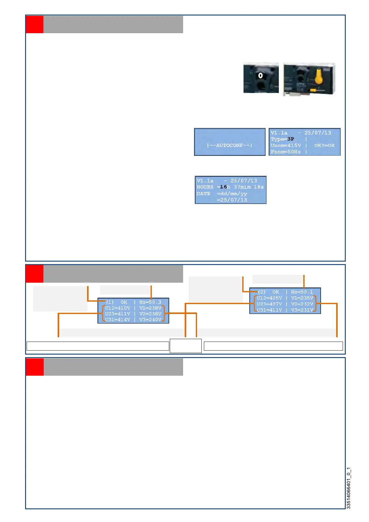
4- Close the mains circuit breaker, voltage will now be present on the source side, auto-configuration will be
initiated and, if the phase rotation is correct (LED [1] off), the switch will automatically switch to position 1
(source 1) and LED [11] will turn green.
The AUTOCONF screen will appear for several
seconds, followed by a screen showing the main
parameters associated with the automatic system
(flashing of the first parameter). These three
parameters must be controlled (Type, Unom, Fnom).
5- Press OK to validate each parameter, or modify them if necessary using or .
6- If necessary adjust the time and date by pressing
or . Press OK to move on to the next value or to
validate each entry.
The default screen showing electrical measurements (see paragraph 11) will now appear.
If the phase rotation is not correct (LED [11] turns red), open the mains breaker and restore the phase
sequence. Go back to the previous operation.
7- Start up the genset in MANUAL mode and close the genset circuit breaker, check voltage and phase
sequence. If phase rotation is not correct (LED [12] turns red) open the genset breaker and restore phase
sequence.
Commissioning
10
Source 1 present
and parameters are
correct
Frequency source 2
Voltages (phase to neutral) of type 3P+N Phase voltage (between phases) of type 3P+N
Electrical measurements display
11
Displays may be different depending on type of system
Frequency source
Source 2 present
and parameters are
correct
These two screens are displayed one after the other (*)
LAMP TEST = Functional test of all LED’s and the screen,
STATS = Record of the number of operating hours of each source ((1)=xxxH, (2)=xxxH), and the number of
transfers from one source to another ((1)->(2)=xx, (2)->(1)=xx),
EVENTS = Record of all the events that have occurred regarding the operation of the transfer switch (alarms,
faults, test mode etc…),
MAINT = Access to two telephone numbers in case of operating problem,
PARAM = Access to switch parameters (see Attachment 1, § A11, list of parameters),
TIMER = Access to switch timer (See Attachment 1, § A12 list of timers),
PROGRAMS = Access to programmed functions (See Attachment 2, § A23),
I/O = Access to programming of inputs and outputs of the electronic card (See Attachment 2, §A22),
AUTOSET = Access to automatic configuration of the transfer switch,
RS485 = Access to serial link parameters
INIT = Restore factory settings + AUTOSET
FACTORY = Access to traceability information (serial number, software version), access to time and date
settings, access to USB drive
Available menus
12
(*) if source
2 present
 Loading...