57
amplitude should be less than 10mm
2.9 50Hz Anti-interference filter ≥20dB
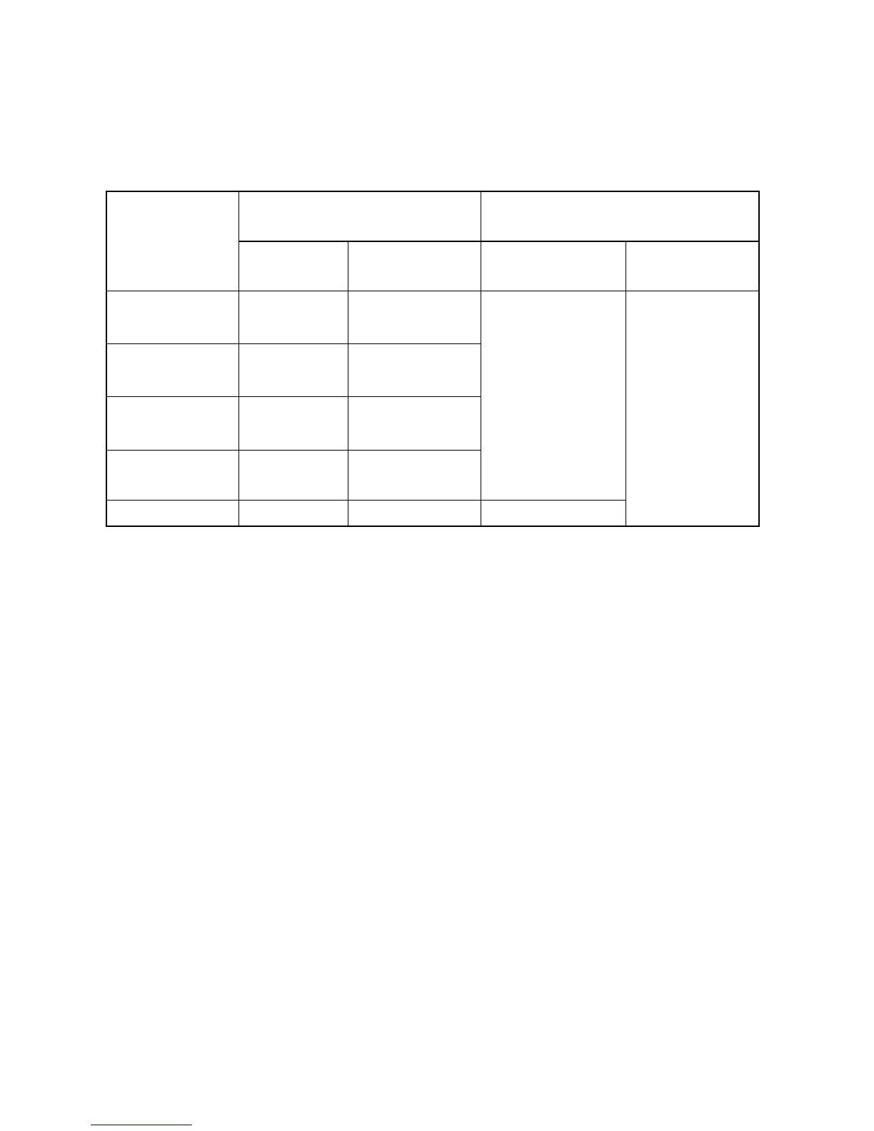
Table1 Input Impedance
Lead Electrode
The summit value of deflection front
traced by K open circuit (mm)
Lead Position
Connecting
to P1
Connecting to
P2
Single Channel ECG Multi-channel ECG
Ⅰ,Ⅱ,aVR, aVL,
aVF,V1
R
All other Lead
electrodes
Ⅰ,Ⅲ,aVL, aVR,
aVF,V2
L
All other Lead
electrodes
Ⅱ,Ⅲ,aVF, aVR,
aVL,V3
F
All other Lead
electrodes
Vi(i is 1~6)
Ci
All other Lead
electrodes
8
Vx, Vy, Vz A,C,F,M I, E, H —
8
2.10 Features of Amplitude Frequency
When the filter is shut off, take 10Hz sine wave as reference.
From 0.5 to 50Hz, the tolerance of amplitude of frequency is -10%~+5%.
From 50 to 70Hz, the tolerance of amplitude of frequency is -30%~+5%
2.11 Features of Low Frequency .Time Constant no less than 3.2s
2.12 Baseline stability
2.12.1 Stable Power: baseline drifting should be no more than 1mm
2.12.2 Unstable Power: baseline drifting should be no more than 1mm
2.12.3 Sensitivity (no signal input) : baseline drifting should be no more than 2mm
2.12.4 Temperature Drift: From 5~40℃, baseline drifting should be no more than 0.5mm/℃
2.13 Paper Speed
Should have 25mm/s and 50mm/s at least , tolerance:±5%
2.14 Multi-channel Crosstalk for Multi-channel ECG
The Multi-channel crosstalk should less than 0.5mm between any channels of the multi-channel
ECG.
2.15 Influence of AC-DC converts
When the power supply is converted from AC to DC, the indicator light for DC work mode will on.
2.16 Printing resolution (Thermal matrix printing)