14 Assembling the SmartServer Hardware
Pulse Meter Inputs
The SmartServer includes two impulse meter inputs that comply with the DIN 43 864 impulse standard
(open terminal voltage <12VDC, maximum current ≤27mA). The pulse meter input connections are
implemented on screw terminals 9–12: Meter 2 is connected to terminals 9-10; Meter 1 is connected to
terminals 11-12. These connections are polarity-sensitive: terminals 9 and 11 are marked positive (+),
and terminals 10 and 12 are marked negative(-). You cannot reverse the polarity of the pulse meter
inputs because it will cause improper operation of the measurement circuits.
Each of the pulse meter inputs is controlled by a Pulse Counter application on the SmartServer. A
pulse input meter registers a pulse when the circuit between its positive and negative connections is
closed (the voltage is 0) for 30ms or longer. The circuit must be open for a minimum of 30ms between
pulses. See Chapter 9 of the i.LON SmartServer User’s Guide for configuring the SmartServer to use
the pulse meter inputs to which it is connected.
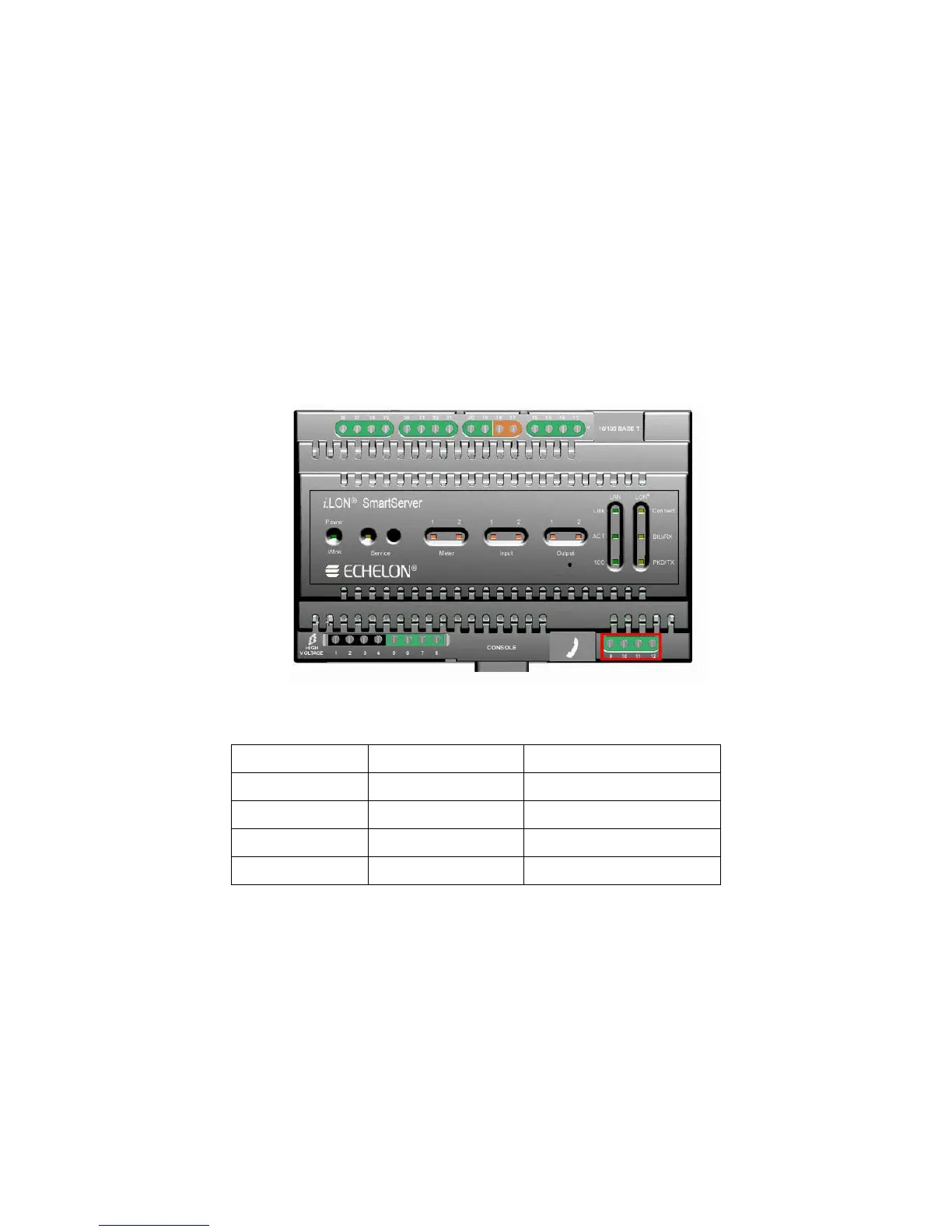
The following figure illustrates the location of the pulse meter input screw terminals on the
SmartServer.
The following table lists the enclosure markings for the pulse meter input screw terminals on the
SmartServer and their connection type.
Screw Terminal Enclosure Marking Pulse Meter Connection
9 Meter2- - Signal from Meter 2
10 Meter 2+ +Signal from Meter 2
11 Meter 1- - Signal from Meter 1
12 Meter 1+ + Signal from Meter 1
You can connect the pulse meter inputs on the SmartServer to either a dry contact relay, or to an active
device output that generates pulses by closing the circuit between the two terminals. The following
figure demonstrates both of these configurations.