20
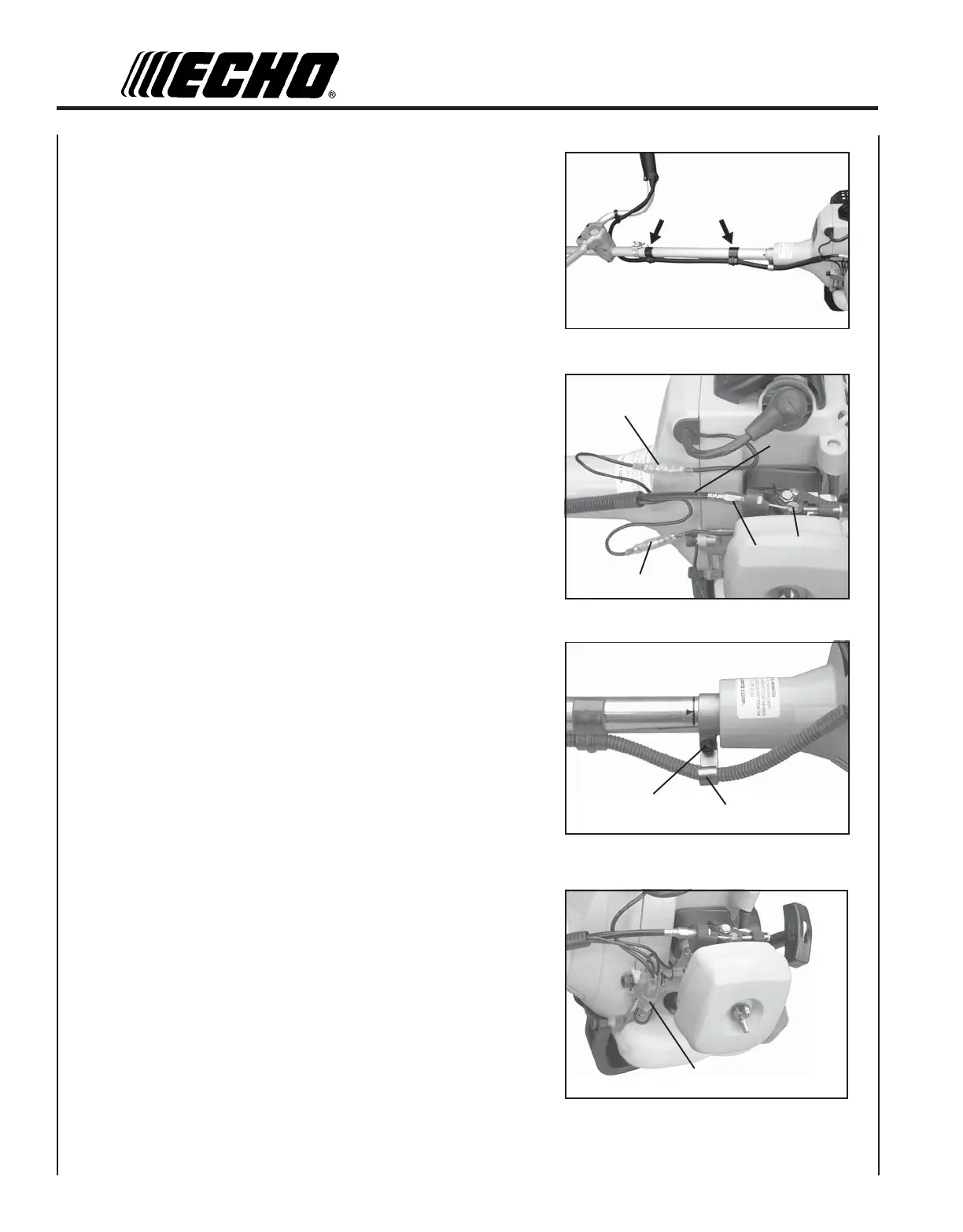
12. Route throttle linkage and ignition lead assembly along shaft and
clip as shown.
13. Place throttle linkage (D) through adjustment fixture (E) and install
wire end into large carburetor throttle swivel hole (C). Check
throttle for freedom of movement and that wide open throttle / low
idle extremes are adjusted properly. The throttle linkage must be
adjusted by moving the adjustment fixture (E). Consult with your
Echo Dealer for correct adjustment procedure.
14. Connect ignition leads (A) and (B).
15. (SRM-231) Remove left side clutch case bolt (M). Install metal
bracket clamp (N) with curved end up.
16. (All Models) Install throttle linkage into bracket clamp and pinch
tight with pliers. Bend bracket up and flush against drive shaft.
17. Bundle and secure ignition leads against engine housing with clip
(O).
M
N
A
B
D
E
C
O