31
SRM-330ES/SRM-350ES
E
N
G
L
I
S
H
D
E
U
T
S
C
H
I
T
A
L
I
A
N
O
DESCRIPTION
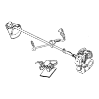
10 THROTTLE TRIGGER Activated by the operator’s
finger for controlling the engine speed.
11 THROTTLE TRIGGER LOCKOUT Locks throttle
trigger in the idling position until you have a proper
grip with your right hand around the handle.
12 AIR CLEANER COVER Covers air filter.
13 FUEL TANK Contains fuel and fuel filter.
14 FUEL TANK CAP For closing the fuel tank.
15 STARTER HANDLE Pull handle to start the engine.
(“ES” START)
16 SILENCER COVER Cover the silencer not to make
operator touch to hot surface of silencer.
17 PURGE BULB
18 SPARK PLUG
19 RETAINING PARTS
20 SHOULDER HARNESS An adjustable straps to
suspend unit.
21 HIP PAD To protect hip/leg and clothing.
22 BLADE COVER When transporting the unit, use the
appropriate metal blade cover.
23 SAFETY DECAL Part number 890617-43130
GB
(See page 30)
1 OPERATOR’S MANUAL Included with unit. Read
before operation and keep for future reference to
learn proper, safe operating techniques.
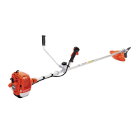
2 ANGLE TRANSMISSION Having two gears to change
the angle of rotating axis.
3 CUTTING ATTACHMENT Nylon line head for cutting
grass and weed.
3(U) CUTTING ATTACHMENT 3 cutter blade for cutting
grass, garden debris and weeds.
4 SHIELD Device to protect the operator from accidental
contact with the cutting head and thrown objects.
5 CUT OFF KNIFE Cut nylon line to adjust line length
to proper swath.
6 SHAFT TUBE Part of the unit that provides a casing
for power transmission shaft.
7 LOOP-HANDLE Light weight, suitable for Nylon line
trimmer.
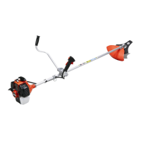
7(U) U-HANDLE Having the configuration of a bicycle
handle bar to reduce working effort compared to a
loop-handle.
8 SUSPENSION POINT Device on which the harness
can be hooked.
9 IGNITION SWITCH “Slide Switch” mounted on top of
the Throttle Trigger Housing, move switch forward to
RUN, backward to STOP position.
9(U) IGNITION SWITCH “Slide Switch” mounted on top of
the Throttle Trigger Housing, move switch upward to
RUN, downward to STOP position.