1. Loop
handle
2.
Screw M5x35
3. Loop handle bracket
4. Nut
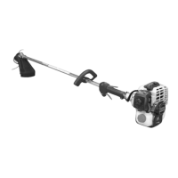
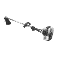
LOOP HANDLE
Assem bie
loop
handle and bracketto
drive shaft
assembly.
Position handle in comfortable
operating
position
and
tighten screws.
1. Linker Hand Griff
2. Schraube M5x35
3.
Befetigungs Platte
4. Muiter
RUNDGRIFF VERSION (L-TYP)
Rundgriff und
Halterung leicht
an der Antriebswelle
befestigen.
Griff in einer bequemen Arbeitsstellung anbringen und die
Schrauben festziehen.
1. lmpugnatura anteriore
2. Vite
M5x35
3.
Supporto
4. Dada
IMPUGNATURA AD
ANELLO
Montare
l'impugnatura e la staffa senza stringere
sull'albero motore.
Regolare l'impugnatura
in una
posizione
di
lavoro
confortevole e
serrare Ie viti.
SRM-3805
1.
Bracket 4. Fitting
plate
2. Bolt M5x25
5. Notch of fitting plate
3. Convex of fitting
plate
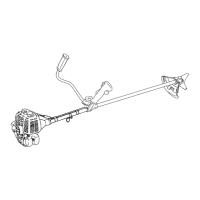
INSTALLATION OF BRACKET
Fit bracket to
mounting portion of angle
transmission and
fix the bracket by
holding fitting plate pressed !rom beneath
and tightening 4 balts ( M5x25 ) lightly.
Ge! notches and convexes of fitting plate
to
face
corresponding convexes and concaves of bracket, and fix
bracket
tightening 4 balts securely.
1. Runge
2. Schraube M5x25
3. Fixierungspunkt in der
Befestigungsplatte
4. Befestigungsplatte
5. Kerbe in der
Befestigungsplatte
ZUSAMMENBAU DER RUNGE
Befestigen Sie die
Runge am Winkelgetriebe
indem
Sie
die
Befestigungsplatte
von
unten dagegen drücken und
die
4
Schrauben (
M5x25
)
leicht
anziehen.
Bringen Sie die Kerbe
und den
Fixierpunkt der
Befestigungsplatte
au! dàs entsprechende Gegenstück
der Runge und ziehen Sie die 4 Schrauben
lest.
1. Supporto
2.
Bullone M5x25
3. Convesso della
piastra
di raccordo
4. Piastra di raccordo
5. 1 ncavo della piastra
di raccordo
MONTAGGIO DEL SUPPORTO
Adattate il supporto alla parte di montaggio della testina e
fissate il supporto tenendo
la
piastra di raccordo premuta
verso il basso e stringendo Ie 4 bulloni
(
M5x25 }, ma non
troppo.
Fate combaciare gli incavi e i convessi della piastra di
raccordo in modo che convessi e
concavi
del supporto
corrispondano
e
fissate
il supporto stringendo
bene Ie
4
bulloni.
36
{ ©
,1)
='-- '
---- -= .
3
- -)...,
-2
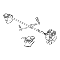
1. Bracket
4.
Cut off knife
2. Shield
5.
Screw
M5x12
3. Screw M5x18
There are
two
types of shields: namely one used
exclusively tor
Nylon card and
another one used
exclusively tor
steel blade. When Nylon
card is used,
use the shield tor Nylon card. When steel blade is used,
use the shield forsteel blade.
METHOD
TO CHANGE
SHIELD
Remove screw (5x18) on the right side of the shield
and slide the shield to the lelt and remove it. Put shield
of another type into groeve and slide
it to
the right until
it stops and be sure to
lasten
with the
removed
screw.
1, Runge
4. Fadenschneidmesser
2.
Schutzschildes
5. Schraube M5x12
3. Schraube M5x18
Es
gibt zwei unterschiedliche Schutzschilde: Der eine
Schultzschild wird
bei
Verwendung des
Nylon
Fadenkopfes, der Andere bei Verwendung von
Metallblättern eingesetzt. Wenn Sie mi!
dem
Nylon
Fadenkopf arbeiten, verwenden Sie den Schutzschild
für den Nylon Fadenkopf. Wenn Sie Metallblätter
einsetzen verwenden Sie den Schutzschild für
Metallblätter.
WECHSELN DES SCHUTZSCHILDES
Entfernen Sie die Schraube
(M5x18)
an der rechten
Seite des Schutzschildes,
schieben Sie den
Schutzschild nach links und nehmen ihn ab. Den andere
Schutzschild in der Führung nach rechts bis Anschlag
schieben
und mil der Schraube
(5x18)
sichem.
1, Supporto
4. Coltello taglialilo
2. Protezione
5. Vite M5x12
3. Vite M5x18
Ci sono due tipi
di
protezione per i decespugliatori:
quella utilizzata esclusivamente con testina a lila di
nylon, e quella utilizzata solo per il taglio con disco.
Si
raccomanda
quindi di utilizzare Ie protezioni in
abbinamento
con l'apparato di taglio adeguato.
SOSTITUZIONE DELLA PROTEZIONE
Allentare e
rimuovere la vite (5x18) sul lato destro della
protezione, facendola scorrere in avanti lino allo
sgancio definitivo. Quindi posizionare la nuova
protezione nello stesso punto,
facendola scorrere sulla
destra fino in fondo
1
assicurandosi che sia
correttamente in posizione prima
di
serrare
nuovamente
la vite rimossa in precedenza.
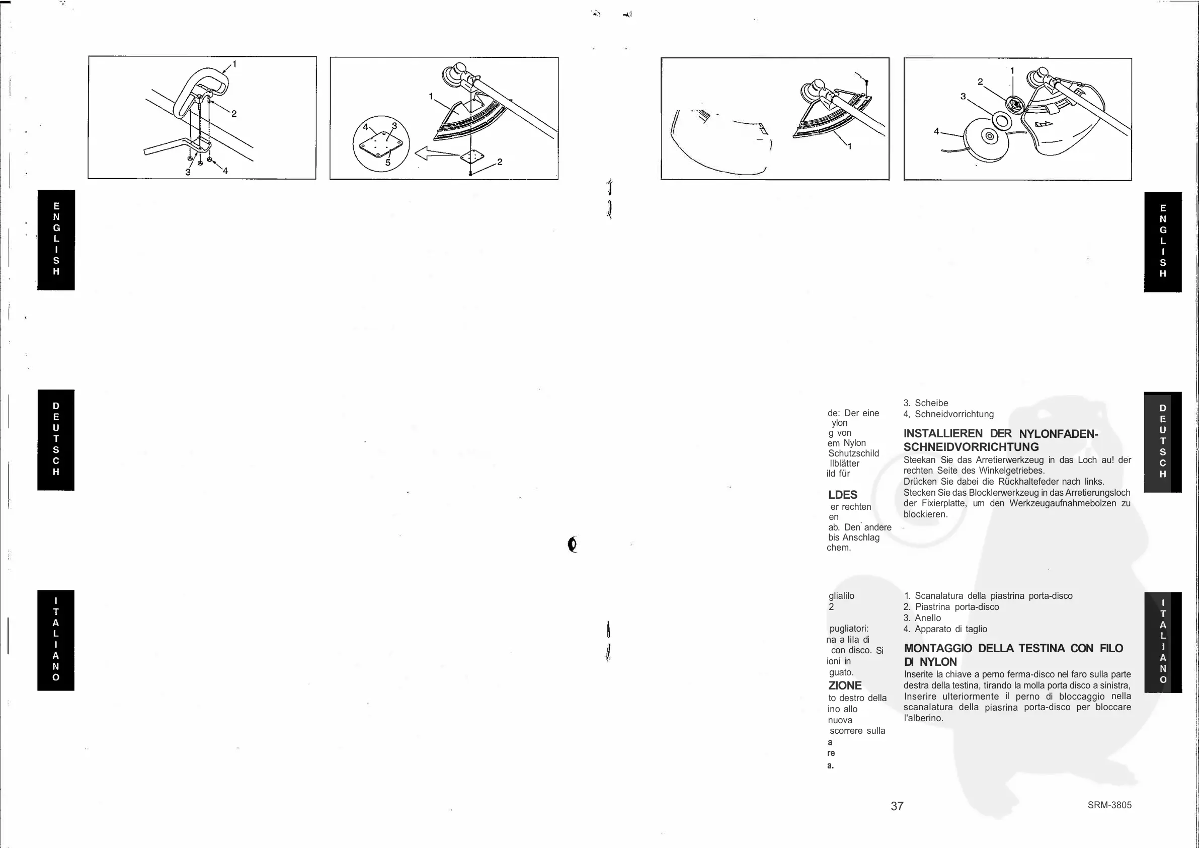
1. Blade
retainer fixing
slot
2. Blade retainer
3. Washer
4. Nylon line
cutting
attachment
INSTALLING
NYLON
LINE
CUTTING
ATTACHMENT
lnsert locking
tool into a hole
located
on
the right side of
angle
transmission while forcing
retainer
spring to the lelt
side. lnsert locking tool further into blade retainerfixing slot
to fix output shaft.
1.
Arretlerungsloch-Fixierplatte
2. Fixierplatte
3. Scheibe
4, Schneidvorrichtung
INSTALLIEREN DER
NYLONFADEN-
SCHNEIDVORRICHTUNG
Steekan Sie das Arretierwerkzeug in das Loch au! der
rechten Seite des Winkelgetriebes.
Drücken Sie dabei die Rückhaltefeder
nach
links.
Stecken Sie das Blocklerwerkzeug
in das
Arretierungsloch
der Fixierplatte, urn den Werkzeugaufnahmebolzen zu
blockieren.
1. Scanalatura della piastrina porta-disco
2. Piastrina porta-disco
3. Anello
4. Apparato di taglio
MONTAGGIO DELLA TESTINA CON FILO
Dl
NYLON
lnserite la
chiave
a perno ferma-disco nel faro sulla parte
destra della testina, tirando
la
molla porta disco a sinistra,
lnserire ulteriormente
il
perno di bloccaggio
nella
scanalatura della
piasrina
porta-disco per bloccare
l'alberino.
37
SRM-3805
 Loading...