4
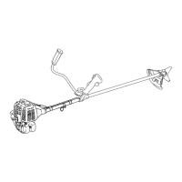
1.
Right
hand U-handle
2. Wire fixing clip
3. Shaft tube
4. Throttle wire
To eliminate
loosening of
throttle
wire fix
il to
shaft
tube
( 2 places)
and to right hand
U-handle ( 1
place) with wire
fixing
clips.
1.
Rechter Handgriff
2.
Kabelklemme
3. Kabelhülle
4.
Gaszug
Urn zu
verhindern, daB sich der Gaszug
löst, fixieren Sie
ihn
am Schaft mit 2 Kabelklemmen und am
rechten Grill
mil
einer Kabelklemme,
wie nebenstehend abgebildet.
1. lmpugnatura destra ad
U
2. Fenno cavo
acceleratore
3. Tubo albero
trasmissione
4. Cavo
acceleratore
Per evitare l'allentamento del
cavo acceleratore
fissatelo
al tubo
dell'albero ( 2 posizioni
) e all'impugnatura destra
ad U ( 1 posizione
) con
i
fermi
di fissaggio.
SRM-3805
44
1. Bracket
4. Fitting plate
2.
Bolt M5x25
5. Notch of
fitting plate
3. Convex of
fitting plate
INSTALLATION
OF BRACKET
Fit bracket to mounting
portion of angle
transmission and
fix the bracket
by
holding fitting plate
pressed
trom beneath
and tightening 4 bolts (
M5x25) lightly.
Gel notches and
convexes of fitting
plate
to
face
corresponding
convexes and concaves of bracket, and
fix
bracket
tightening 4 bolts
securely.
1.
Runge
2. Schraube
M5x25
3. Fixierungspunkt
in der
Befestigungsplatte
4.
Befestigungsplatte
5.
Kerbe
in der
Befestigungsplatte
ZUSAMMENBAU DER
RUNGE
Befestigen Sie die
Runge am
Winkelgetriebe indem
Sie
die Befestigungsplatte
von
unten dagegen drücken und
die 4 Schrauben
(
M5x25 )
leicht anziehen.
Bringen Sie die
Kerbe
und
den
Fixierpunkt
der
Befestigungsplatte
auf äas entsprechende
Gegenstück
der Runge
und ziehen Sie die 4 Schrauben
lest.
1.
Supporto
2.
Bullone
M5x25
3. Convesso della piastra
di raccordo
4.
Piastra di
raccordo
5. lncavo della
piastra
di raccordo
MONTAGGIO
DEL
SUPPORTO
Adattate il supporto alla
parte di montaggio
della testina
e
fissate
il supporto tenendo la piastra di
raccordo
premuta
verso il basso e stringendo
Ie 4 bulloni
( M5x25 ),
ma non
troppo.
Fale
combaciare gili incavi e i convessi
della
piastra di
raccordo in modo che convessi
e concavi
del supporto
coprispondano e fissate il
supporto
stringendo
bene
Ie 4
bulloni.
,,
(l
co
0
3
2
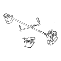
1. Bracket
3.
Screw M5x18
2.
Shield
There are two types of
shields:
namely one used
exclusively lor Nylon cord and
another one used
exclusively lor steel blade. When Nylon
cord is used,
use the
shield lor Nylon cord. When
steel blade is used,
use the
shield forsteel
blade.
METHOD
TO CHANGE SHIELD
Remove screw (5x18) on
the right
side of
the
shield
and slide the shield to the lelt and
remove it.
Put shield
of another type into groove and
slide il
to
the right
until
it stops
and be sure to tasten with
the removed screw.
When
using
Nylon
cord, use the shield lor Nylon cord.
(see P.37) Fit cord knife
to the shield
lor
Nylon cord
using screw
(5x12).
1. Runge
3. Schraube M5x18
2. Schutzschildes
Es gibt zwei unterschiedliche
Schutzschilde:
Der eine
Schultzschild wird bei Verwendung
des
Nylon
Fadenkopfes, der Andere
bei Verwendung
von
Metallblättern
eingesetzt. Wenn Sie
mit
dem
Nylon
Fadenkopf
arbeiten,
verwenden Sie den
Schutzschild
für den Nylon Fadenkopf. Wenn Sie
Metallblätter
einsetzen verwenden Sie
den Schutzschild
für
Metallblätter.
WECHSELN DES SCHUTZSCHILDES
Entfemen
Sie die Schraube (M5x18)
an der rechten
Seite des
Schutzschildes., schieben
Sie den
Schutzschild
nach links und
nehmen ihn ab. Den
andere Schutzschild in
der Führung
nach rechts bis
Anschlag schieben und mil der
Schraube (5x18)
sichern.
Wenn
Sie mit dem Nylon Fadenkopf
arbeiten,
verwenden Sie das Schutzschild
für den Nylon
Fadenkopf. (siehe Seite.37)
Befestigen Sie
den Fadenabschneider am
Schutzschild
für den Nylon
Fadenkopf mil Schrauben
(M5x12).
1.
Supporto 3. Vite
M5x18
2. Protezione
Ci sono due
tipi di protezione per
i decespugliatori:
quella utilizzata esclusivamente con
testina
a
filo di
nylon, e quella utilizzata solo per
il taglio con disco.
Si
raccomanda
quindi
di utilizzare Ie protezioni
in
abbinamento con l'apparato
di taglio adeguato.
SOSTITUZIONE
DELLA
PROTEZIONE
Allentare e rimuovere
la vite (5x18)
sul lato destro della
protezione, facendola
scorrere in avanti
lino allo
sgancio definitivo. Quindi
posizionare
la nuova
protezione nello stesso punto, facendola
scorrere
sulla
destra fino in fondo
1
assicurandosi
che sia
correttamente in posizione prima
di serrare
nuovamente la vite
rimossa in precedenza.
Quando si
utilizza la testina
a
filo,
munire
il
decespugliatore di protezione
apposita per questo
tipo
di apparato di taglio. (Vedi
pag. 37)
Posizionare la
lametta taglia-filo sulla
protezione per
testina, utilizzando la vite
in dotazione
(5x12).
45
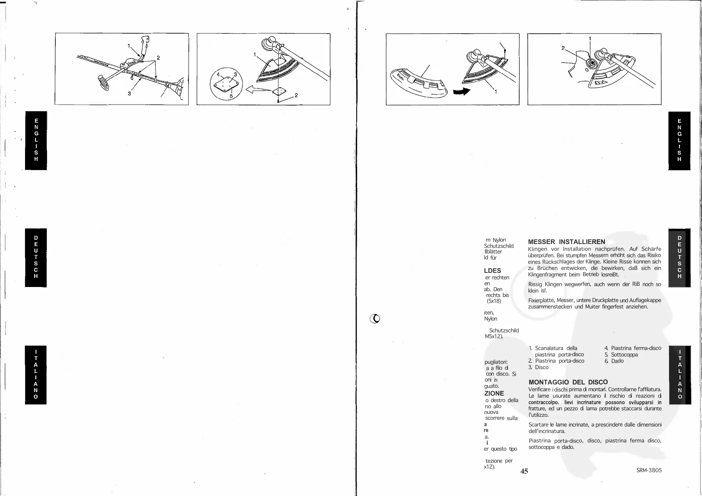
3
4
5
6
1. Blade retainer fixing
slot
2. Blade retainer
3. Blade
INSTALLING
BLADE
4.
Lower
blade retainer
5.
Cup
6. Nut
Inspeel blades belore
installation.
Check tor sharpness.
Dull blades increase
the risk
of blade kick-back reactions.
Small cracks
can develop into fractures
resulting in a piece
of blade flying
off during operation.
Discard
cracked blades no matter how
small the crack.
Blade retainer,
blade, lower
blade retainer, cup and nut
finger light.
1. Arretlerungsloch-Fixierplatte
4. untere Druckplatte
2.
Fixierplatte
5. Auflagekappe
3. Messer
6. Muiter
MESSER INSTALLIEREN
Klingen vor lnstallation nachprüfen.
Auf Schärfe
überprüfen. Bei stumpfen Messern erhöht
sich das Risiko
eines Rückschlages der Klinge. Kleine
Risse können
sich
zu Brüchen entwicken, die
bewirken,
daB sich ein
Klingenfragment beim Betrieb
losreiBt.
Rissig Klingen wegwerfen,
auch wenn
der
RiB
noch so
klein is!.
Fixierplatte, Messer, untere
Druckplatte
und Auflagekappe
zusammenstecken
und Muiter fingerfest
anziehen.
1. Scanalatura
della
piastrina porta-disco
2. Piastrina porta-disco
3. Disco
4. Piastrina ferma-disco
5. Sottocoppa
6. Dado
MONTAGGIO DEL DISCO
Verificare
i dischi prima di montarl. Controllarne
l'affilatura.
Le lame
usurate aumentano il rischio
di reazioni
di
contraccolpo.
lievi incrinature
possono
svilupparsi in
fratture,
ed un pezzo di lama potrebbe
staccarsi
durante
l'utilizzo.
Scartare Ie lame incrinate, a prescindere
dalle dimensioni
dell'incrinatura.
Piastrina
porta-disco, disco, piastrina
ferma disco,
sottocoppa e
dado.
SRM-3805
 Loading...